
TL;DR
Europe Card Bus (ECB) is a Retro CPU Bus standard from the late 1970’s / early 1980’s.
The “Minimalist Europe Card Bus” (as I call it), is a Retro 8-bit CPU Bus based PCB design standard that I decided to define & document. The purpose of which is to provide a modular platform for me to re-experience the fun of experimenting with the different 8-bit CPU’s, and the various video and peripheral devices, that I grew up with in the late 1970’s and early 1980’s.
My goal is that of a robust and modular design platform which would allow me to create interchangeable boards, based on time proven reliable bus connectors and modern low-cost prototype PCB manufacturing.
i.e. A robust, flexible, and low cost way for me to re-create some of the early microprocessor circuits, that I’d originally built using Wire-Wrap methods back in the day.
As evident from the name, the Bus itself is based on a Minimalist implementation of the original Europe Card Bus (ECB) standard.
Join me for an Introduction of MECB, and the Background that lead me down this path. Also, a few previews of some of the MECB boards I’ve been developing, to date.
Background
Vero Square Pad Eurocard boards, Wire-Wrap and DIN 41612
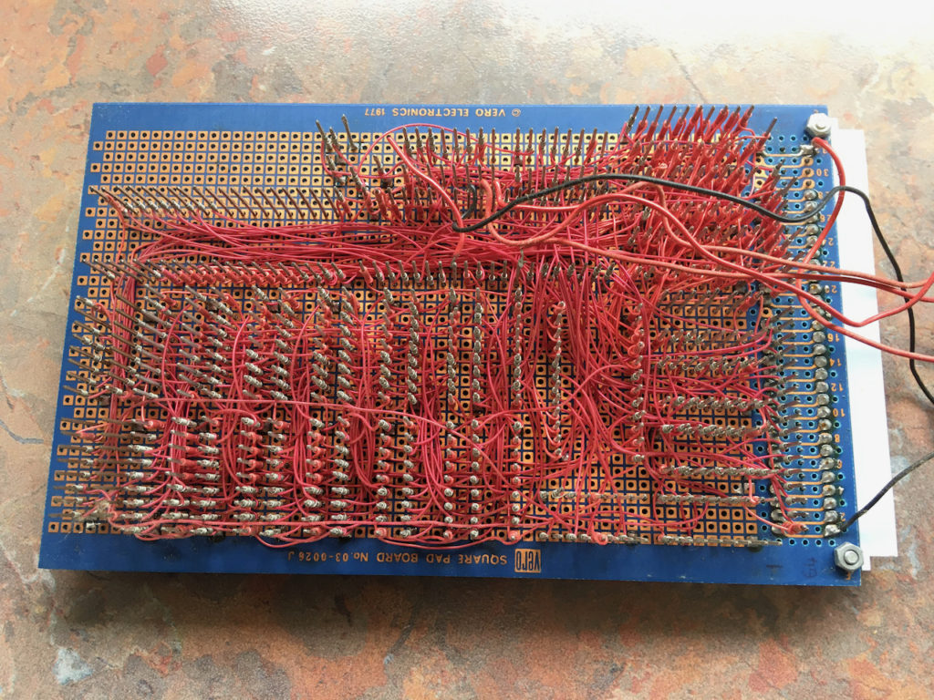
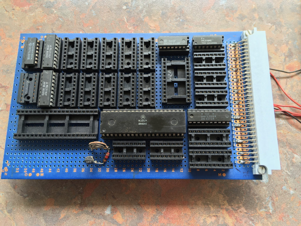
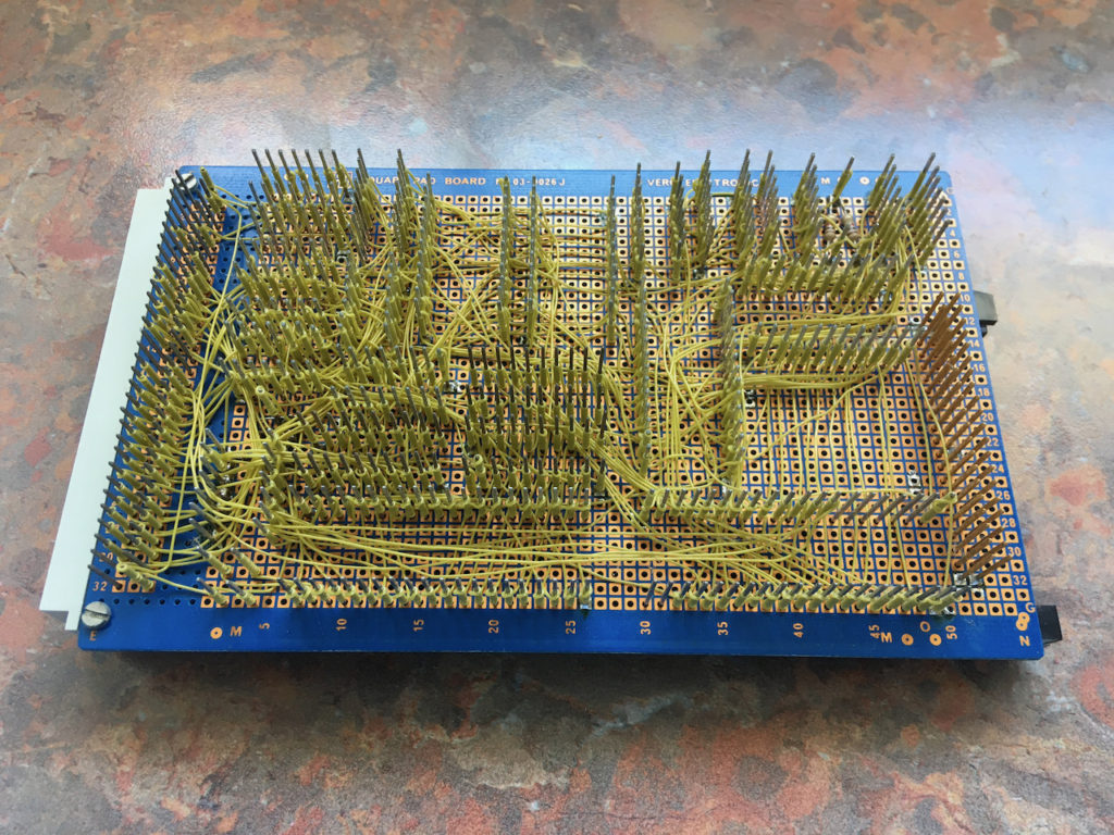
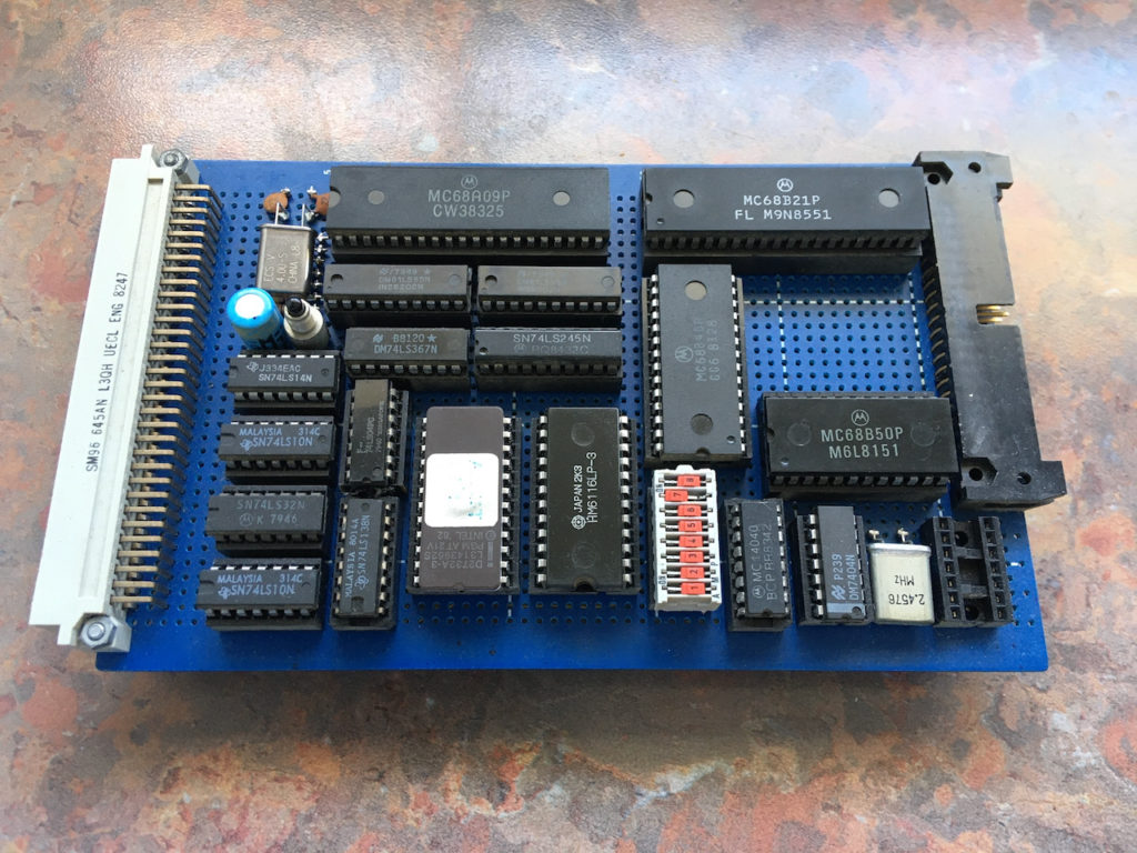
A long time ago (back in the early 1980’s), I developed my first microprocessor system designs around the Motorola MC6809. I built these systems using Vero Square Pad Eurocard boards, with Wire-Wrap and DIN 41612 bus connectors.
Back then, this approach was the optimal way of building homebrew microprocessor and digital circuits. This was a time when PCB design for hobbyists involved having to manually lay-out tape on transparent film, then using UV lights to expose home photo-sensitised copper laminate, before ferric chloride etching. There was no through-hole plating, no HASL surface plating, no solder mask, and certainly no pretty silk screen available to us “low budget” hobbyists! Simply a roughly etched copper laminate board with exposed (and oxidising) copper!
Yes, hobbyist PCB design in the early 80’s was a manual, time consuming, and also messy process. It also wasn’t very well suited for creating the densely packed layouts for Microprocessor circuit designs with supporting TTL digital logic, which you were wanting to fit onto the standard 3U format 160mm x 100mm Eurocards!
In recent times I’ve rediscovered some of my old wire-wrap boards. These had been packed away in storage boxes for half a lifetime. This got me thinking about possibly re-creating some of my old designs using modern PCB’s instead.
Introduction
Deciding on a Bus and Board Design
I considered my various retro boards and also the various peripheral chips that I had in storage. Also, I considered my original Eurocard based Bus approach.
I decided that instead of just re-creating my existing wire-wrap board designs onto fresh modern PCB’s, I really should revisit the custom Bus that I’d used and also ensure that I followed a nice modular and flexible approach.
So, it wasn’t just a case of re-creating some old wire-wrap 8-bit designs onto PCB’s. I really wanted to create a modular design standard that would allow me to experiment with different video display chips, different peripheral devices, and also different CPUs etc.
To use a common idiom, I wanted to be able to “mix and match”.
Of course, I’m aware of the more recent RC2014 retro modular design approach. But, given my early experience using quality Eurocard boards with their professional & robust DIN 41612 connector based Bus solution, there were a number of significant aspects about RC2014 that did not appeal to me.
Specifically, what doesn’t apeal to me about RC2014:
- The use of the less than robust pin header strips, as the basis of the Bus backplane.
- That the Bus connector is not keyed, requiring the RC2014 boards to have a cut off corner design to help identify the correct orientation (and hopefully not inadvertently plugging in the boards backwards).
- That the original 39/40 pin header strip Bus has evolved into a double-row, requiring the added second layer of wider right angle headers (making board insertion even more “fun?”).
Of course, RC2014 does have some benefits:
- An existing range of available boards to play with.
- The low cost of pin headers as a bus solution.
One thing that I did want was a low cost solution! After all, we hobbyist makers don’t always have a lot to fund our hobby!
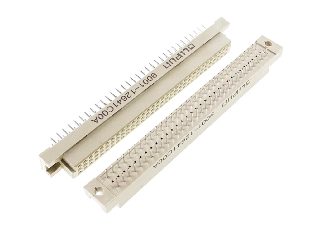
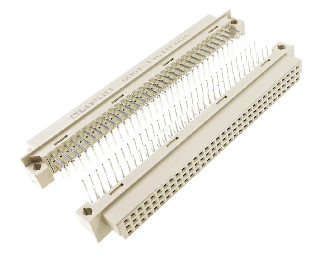
Looking at Mouser, for the current prices of the highly desirable DIN 41612 connectors, I discovered they were rather expensive at around $7 (or more) per connector. But, after a quick search of eBay and AliExpress, I discovered that very affordable connectors are indeed available. Especially in the lower cost 64-pin A&C 2 row variant, as opposed to the full 96-pin ABC 3 row DIN connectors.
So, this satisfied my “low cost” robust connector requirement. Sure, even a DIN 41612 connector sourced from AliExpress is a little more expensive than a 40-pin header strip. But, spending a dollar (or two) gets you a keyed, robust, easy to insert, and industry proven Bus connector solution. This small cost seems, to me, to be perfectly justifiable and a relatively trivial cost in the scheme of things. i.e. Relative to the overall cost of all the parts that are required for any given board design.
Bus Pin-Out / Connection Standard
The next step was to decide on an appropriate Bus pin-out standard to use.
My old boards, which I’d created in the early 1980’s, just used my own devised non-standard Bus pin-out. This was pretty common in those days. Remembering that in the early 1980’s we had no Internet. Awareness of what others were doing was mostly obtained from printed magazines, User Group get-togethers, and snail-mailed printed newsletters etc. All of this was also generally focussed on reasonably local knowledge. Hobbyist awareness of emerging Bus standards on the other side of the world was, well, limited.
My google research identified the Europe Card Bus (ECB) as the logical stand-out example of a standardised hobbyist maker friendly DIN 41612 microprocessor Bus pin-out.
Wikipedia tells me that the ECB was originally developed in the late 1970’s, or early 1980’s, by a German company KONTRON. It originally utilised the same 64-pin row A&C only DIN 41612 connectors, and was also based on the standard 3U format 160mm x 100mm sized Eurocard PCB’s. i.e. The same PCB standard and DIN connectors that I, and presumably many others around that time, were using for their new microprocessor Bus based designs.
Google also told me that RetroBrew Computers appeared to now be the current home of ECB, and that the current Europe Card Bus standard had since evolved into utilising the full 96-pin 3 row DIN connector.
However, what I was looking for was more of a “Minimalist ECB” requirement, simplified to provide a low cost modular solution for the kind of hobbyist 8-bit microprocessor projects that I had in mind. The ability to create various peripheral boards, with addressing flexibility, to allow mixing these alongside different retro 8-bit CPU boards, for easy exploration and experimentation.
With this in mind, even some aspects of the original KONTRON ECB “two row” design would seem unnecessary. For example, the Z80 specific Interrupt and Bus Request daisy-chaining.
Therefore, I decided on a, let’s just call it “Minimalist ECB” approach, intended to satisfy a couple of simple cost saving features I wanted.
A couple of simple cost saving features I wanted:
- Utilise only the lower cost 64 pin (Row A&C) DIN 41612 type C connectors, and
- Satisfy the 100mm square maximum board size for low-cost prototype PCB manufacturing.
Limiting the board size to 100mm square should be fine with a modular approach, where the intent isn’t to create a Single Board Computer. In addition, although the intention is to use retro through-hole parts, board space savings can likely be made in areas like glue logic and buffers.
A Minimalist ECB Backplane Design
For a modular Bus system, the first thing we’ll need is a Backplane for connecting our boards together.
Retrobrew Computers have a published “Backplane 4” design which fits into my desired “Low cost 10x10cm format” (as they describe).
Technically, I could just use this existing ECB Backplane PCB design, and instead populate it with the cheaper 2 row A&C 64-pin connectors (instead of the prescribed 96-pin ABC 3 row connectors). But, there are a few features that I would like to have, that just utilising the existing “Backplane 4” would not deliver.
A few Backplane features that I would like to have:
- I would like to include a 5th Right Angle DIN connector, to facilitate mounting a board horizontally for ease of access during hardware or software debugging and also for prototype board development etc. In addition, the horizontal connector could also allow for extension of the Backplane.
- I’m not happy with the existing 4-pin Molex disk drive power connector. For a 5V only system in the 2020’s, I’d prefer perhaps a DC Power Connector, perhaps even a USB-C connector for the now common 5V USB Power Supplies. Also, a screw terminal for benchtop or any other desired power connection other than a PC AT / ATX Power Supply.
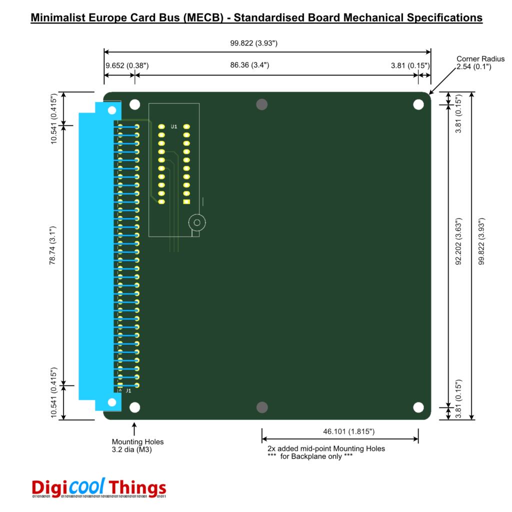
- For consistency, and visual tidiness, I decided that I would first develop a standardised Mechanical Specification for a Minimalist ECB “MECB” board. The specified standard board outline would then form the basis of all MECB boards that I developed, for a tidy, consistent, and attractive complete system solution.
If you consider that my desired Backplane would also include a Right Angle DIN connector on one edge, then it can be seen that a Backplane board can indeed also utilise the same standard mechanical outline as any other MECB board, simply that the backplane board will also carry a row of four vertical connectors.
MECB Board Simplified / Flexible Address Decoding “Glue Logic”
As mentioned earlier, I wanted to be able to create MECB Peripheral boards which implemented addressing flexibility. This is to allow a single board design to be utilised with different retro 8-bit CPU boards, and with different memory maps. This would then support whatever 8-bit CPU based system design I might want to explore and experiment with.
Another consideration is to (ideally) provide simplicity and consistency to the address decoding schematic, which could then be used as a template across different board designs. In addition, minimising the PCB board area required to implement the glue logic, whilst maintaining retro through-hole components.
When reviewing my old-school designs from the early 1980’s, there were typically a small handful of 14-pin and 16-pin TTL packages featuring in each address map specific Address Decoding glue logic.
With this in mind, another important consideration is to reduce the signal load. Hopefully avoiding the need for buffers to drive the bus. A single low power CMOS input would clearly be preferable to the load presented by multiple TTL gate decoding glue logic inputs.
The logical conclusion is to utilise a retro PLD device, which (fortunately), Microchip (ATMEL) still produce as the ATF16V8 and ATF22V10 etc.
Some people may well disagree with this approach, but I believe this is the logical solution for achieving a flexible, but still retro, Address Decoding design.
Some reasons why a simple PLD is a logical Address Decoding solution:
- Address Decoding is about the simplest and most basic use for which you can use a PLD device.
- Designing your Address Decoding logic is as simple as writing the Address Decoding logic statement.
- Programming an ATF PLD chip is just as simple as programming an EPROM or EEPROM.
- Many makers, who are into retro microprocessors, already have a TL866 Programmer in their toolkit (for burning EPROM’s etc).
- Minimal PCB space usage, minimal bus load, and (significantly) full address decoding flexibility is achieved.
The economical 20-pin retro DIP packaged ATF16V8 appears to have all that is needed. This device has 18 pins available, eight of which are I/O and ten are inputs only. In Simple Mode, 2 pins are permanently configured as outputs.
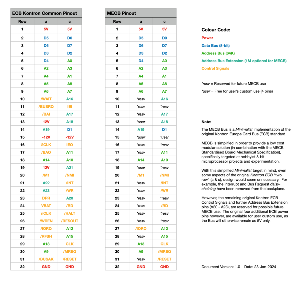
As the ECB Bus utilises the MREQ & IOREQ approach of the Z80 (i.e. a separate I/O address space), my thinking is that for my first design I’ll utilise 15 pins of the ATF16V8 for inputs, allowing up to 3 pins to be used as Chip Select outputs.
PLD is configured with 15 pins as inputs, grouped as:
- The 5 most significant 64KB address lines (i.e. A15 – A11), allowing for memory decoding with 2KB resolution.
- The 5 most significant I/O address lines (i.e. A7 – A3), allowing for I/O decoding with 8 byte resolution.
- And finally, 5 control lines (MREQ, IOREQ, RD, WR, and CLK).
Where this isn’t sufficient for the required decoding, then a board design could (of course), still implement some supplemental gates to complete the glue logic, whilst still maintaining a minimal chip count and still retaining some PLD based Address Map flexibility. Alternatively, some control lines could be swapped out. For example, if RD and WR were not required in the Address Decoding logic, for a particular board design, but perhaps M1 (on a Z80 system) might be desired etc.
By defining an initial ATF16V8 pin allocation assignment, this can then be included in a MECB standard board design KiCAD template, to speed up the process of designing a new board.
If sufficient PCB space is available, it’s also worth ensuring that the space allocated for the ATF16V8 can optionally support a 20-pin ZIF socket, to provide for ease of Address Decoding swap-outs. In this way, when using a peripheral board to experiment with different system configurations, it’ll be easy to just swap out the PLD for different memory map requirements. Of course, if building a more permanent system, then you could just utilise a regular 20-pin IC socket.
With this in mind I have included an ATF16V8 in the KiCAD template, also implementing a standardised PCB layout location with connector clearance to support a 20-pin ZIF socket. If not required, it can (of course), simply be relocated or even deleted from any new board design.
Standardised Mechanical Specification for a Minimalist ECB “MECB” Board
Design Parameters
- Satisfy the 100mm square maximum board size, for low-cost prototype PCB manufacturing.
- Utilise the lower cost 64-pin (Row A&C) DIN 41612 type C connectors, for cost saving.
- Ensure the DIN 41612 connector(s) can be easily centred across the board width, grid aligned.
- Provide two standardised corner holes, on the edge opposing the right-angle DIN connector, to allow for attachment of card handles (to ease board insertion & extraction), or for board mounting – refer next point.
- Provide an additional two standardised corner mounting holes on the edge with the right-angle DIN connector, to provide a full set of four corner holes (to allow for stand-alone board mounting).
- Standardise PCB corner rounding, for sharp corner removal consistency across all boards & visual tidiness.
Design Notes
- PCB layout is designed utilising 0.127mm (5.0 mils) grid setting.
- Board size is 99.822mm, which represents the greatest even multiple of 0.127mm (i.e. multiple of 0.254mm – 10.0 mils), that will fit within the desired maximum 100mm board dimension.
- Standard M3 sized mounting holes were chosen. An additional two mid-edge located mounting holes are specified for the Backplane board only (to provide additional mechanical support).
- For reference, DIN 41612 connectors can utilise standard M2.5 mounting bolts (8mm length for the straight connectors, 10mm length for right angle connectors).
- Implemented as a KiCAD Template, to assist with simplifying the creation of each new MECB board design.
Links
MECB on GitHub – Board Mechanical Specification / KiCAD Template
Hallo I found today this project is close to i had when build my first computer that now rebuild
I have standard 19ich Eurocard case with standard backboard That only thing i still have from original computer.
First part rebuild manual hex keyboard & display & debug board but have problems with IC’s then used you cant buy any more
Greetings TerminEric
Hi Eric. I’ve also got a 19” Euro rack and standard backplane from my early days.
Also, a really nice Hex keypad. I was recently frustrated that it seems impossible to find good quality Hex Keypads these days, so I ended up designing my own, with three configurations. First a cheap version, through to a quality MX key switch based design. I hope to eventually do a video on this topic.
As regards out of production retro ICs, I purchase all of mine via AliExpress. Quality of supply of these recovered chips varies greatly, but usually they’re cheap enough to take the risk of a few non-working chips per order.