
Recently, someone mentioned that they were planning on using a TMS9918 VDP chip, with the MECB TMS VDP Display Card.
As I live in a PAL 50Hz TV standard country, my original experimentation with the TMS VDP chip (and also the chips I had in my parts drawer), were all TMS9929A 50Hz parts.
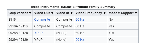
The TMS9929A VDP variant, and its TMS9928A 60Hz “NTSC market” equivalent, feature Color Difference outputs, intended for an external color (colour) encoder circuit.
Join me as I update the MECB VDP Display Card to v2.0, to also add support for the TMS9918A variant.
Devices that used the TMS VDP in the PAL market, typically used the TMS9929A with an external PAL Encoder chip, to deliver a Composite Video signal to an on-board RF modulator, for TV connection.
The mention of the TMS9918 reminded me that, in the NTSC market, the TMS9918A variant would have been the most popular and well known, with its convenient direct NTSC Composite Video output.
Unfortunately, there was no 50Hz PAL equivalent, which (I guess) would have logically been named TMS9919 (if such a device had been released).
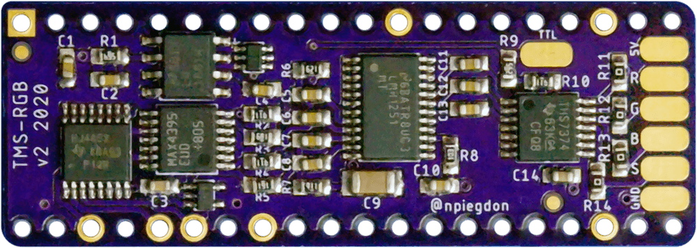
With my TMS9929A background, and of course, my desire for the best possible video quality output, my focus when creating the existing VDP Card, was using the TMS9929A(or TMS9928A), in combination with the recent TMS-RGB module, for a really nice & clean RGBS output.
But, it occurred to me that not everyone (particularly those more familiar with the TMS9918), may want to get hold of a TMS-RGB module, or would necessarily desire the optimal RGBS output quality. Particularly, if they were just wanting to interface to a Composite Video monitor.
With this in mind, I decided I’d enhance the existing MECB TMS VDP Card, to make it an all encompassing TMS VDP solution. A single Card which supports the TMS9929A and TMS9928A (for RGBS output), as well as the TMS9918A with its Composite Video only output.
This then avoids any need for somebody to make a custom Composite Video output solution, to support using a TMS9918 on this Card (for those who want to use it).
So, let’s take a look at the updated schematic.

As you can see, I’ve added a new section, inside a box, to differentiate the additional circuitry desired for supporting the TMS9918 instead.
The Card works just as it did previously with a TMS9929, or TMS9928, and a TMS-RGB module, you simply don’t populate the additional components within the boxed area.

I’ve also added a couple of pre-linked PCB jumpers, to allow easy isolation of this circuit, in the event a TMS9918 user later decides to switch to the TMS9928 (or TMS9929), and TMS-RGB module solution.
Likewise, if the PCB jumpers are cut, it will be equally easy to re-solder-bridge them, if later reverting back to a TMS9918.
As I’d chosen the Sega Mega Drive 2 (MD2) mini-DIN connector standard, for the Video output, we are good to go.
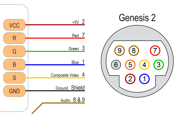
As this connector also includes a pin assignment for Composite Video (as well as RGB), we can use the same existing Card connector for both solutions.
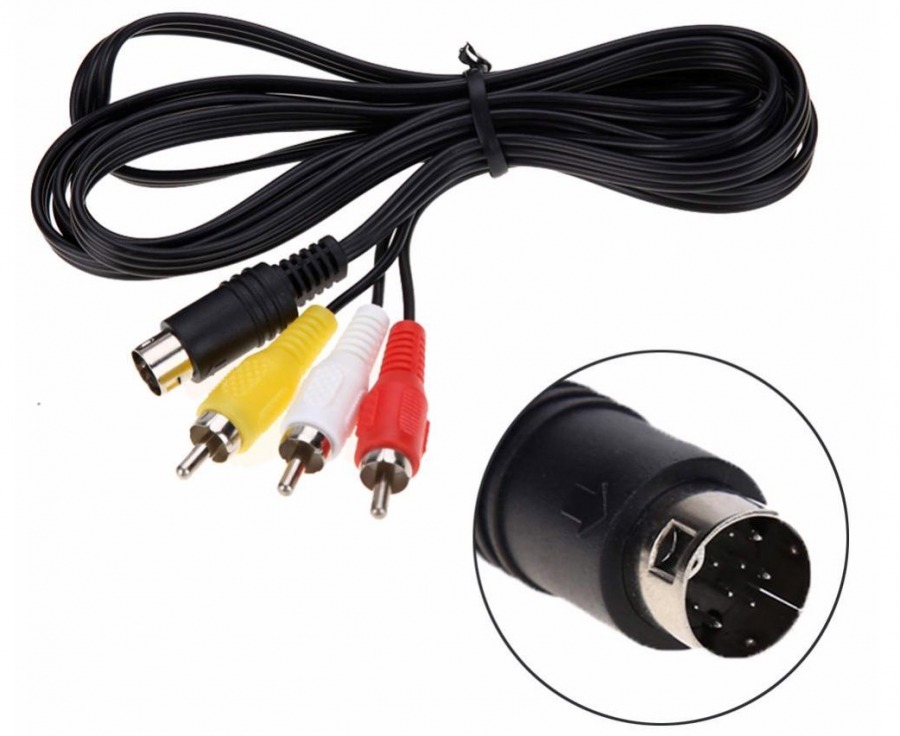
With a TMS9918, obviously the RGB signal won’t be available on the connector, so just an ordinary (cheap & easy to find), Mega Drive 2 Composite Video cable, will do the job nicely.
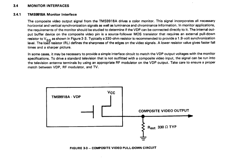
In terms of the additional circuitry, this simply provides a transistor buffer to drive the Composite Video output at an appropriate impedance.
This output circuit being supplied with noise filtered 5V power, via the ferrite bead and capacitors, intended to minimise the presence of digital noise on the video output.
It’s also worth noting that, although it is possible to provide a Composite Video output directly from the TMS9918 chip’s Composite Video output pin, doing so has two downsides.
Firstly, there is no protection for the TMS chip, if directly connecting it to the video output.
Secondly, the typical 75 ohm impedance of a monitor’s video input, puts additional load on the TMS VDP chip, causing to run a hotter.
This is avoided if an external transistor buffer is used, also ensuring the video output impedance is more appropriately matched.
Finally, also note that for a TMS9918 we avoid installing R1 and R3. On the TMS9929 and TMS9928, these resistors are required for the Colour Difference outputs, but on the TMS9918 these 2 pins are an optional video input and a NTSC color burst frequency clock output (3.579MHz).
Both of these pins are unused and can be left unconnected.
So let’s take a look at the PCB layout.

As you can see, the PCB literally just adds the boxed additional components section, which has been clearly labeled with the “TMS9918 Only” silkscreen.
So, to utilise a TMS9918 you just need to populate these additional components, instead of fitting a TMS-RGB module on the reverse side of the PCB (under the VDP).
Oh, and also just leave off R1 and R3.
Simple!
So for a final test of the revised TMS VDP Card, I first pre-built one of the new v2.0 Cards, up to the point of the previously assembled card (in an earlier post/video), so that I could then go ahead with adding the new additional components to test the card with a TMS9918A VDP chip.
Remembering also, to leave-off R1 and R3.
With the original components soldered on, I then went ahead with adding the additional TMS9918 components.
This included the two 75 ohm resistors, the transistor, the capacitors, and lastly, the ferrite bead.
Finally, I soldered on the three Card connectors, being the tallest components.
Now, with the additional components assembled (and no TMS-RGB module attached), I inserted a TMS9918A VDP chip.
I then migrated the other chips over from my existing TMS9929A VDP Card, as these were all “know good” devices, and also my pre-programmed VDP Card PLD.
Lastly, I plugged-in a Composite Video cable to my LCD monitor, using a standard Mega Drive 2 (MD2) Composite Video cable.
Now I was ready for our first test.
So, next I applied power. Then, I transferred the same Initial Test program that I used when testing the original VDP Card.
Then, I ran it!
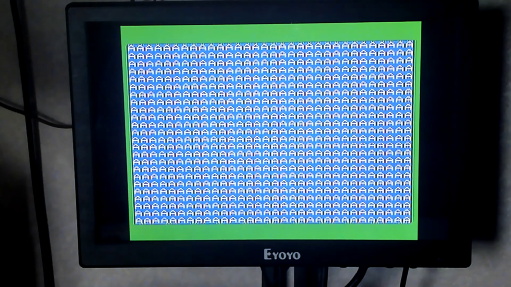
All looks good.
Next, I compared to a similar monitor photo of my TMS9929A RGBS card, to compare the images.

From the 2 photos, you may notice that the displayed image is not as “pixel perfect” sharp as the RGBS output of the TMS9929A, but that is expected, as Composite Video is known for its visual artefacts, which are a result of combining the Luminance and Chrominance components of a video signal.
Also, I’ll mention that these monitor photos really don’t do justice to just how sharp & clean the TMS-RGB module RGBS output really is, when doing a first-hand “with your own eyes” comparison!
But, I’m happy with the result, and I’m sure that this update will be appreciated by those in the NTSC market who are more familiar with the TMS9918 VDP chip.
I’ve now updated the MECB Github repository, and also the Tindie store listing, to reflect the v2.0 changes, and to also add the option of a pre-tested TMS9918A chip and crystal optional pack with your PCB.
So, we now have a TMS VDP Card that satisfies all flavours of this TMS VDP family.
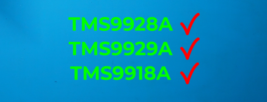
Awesome.