
In a couple of recent posts / videos, I covered the beginnings of my Hexadecimal Keypad design journey.
In these earlier posts, here and here, I presented the history of the project, then I assembled and tested my initial Tactile Switch based budget Hex Keypad design.
The Tactile Switch version Hex Keypad turned out quite nice and is significantly more usable than the cheap membrane keypads that are now generally available.
Also of note, my Keypad implements the standard 0.75 inch (19.05mm) key spacing, something you don’t typically get with small membrane keypads.
Having designed this initial budget Hex Keypad, I then decided that I’d also like to go further, and design my Ultimate Hex Keypad version.
Join me, as I now take you through my design journey to my Ultimate Hex Keypad design.
The idea behind my Ultimate Hex Keypad design was to even improve on the comfort level that I recall I had when using my original mechanical Hex Keypad, back in the 70’s and 80’s.
Also, to provide Keypad assembly flexibility, so that the Keypad can be assembled in different ways, depending on the intended application.
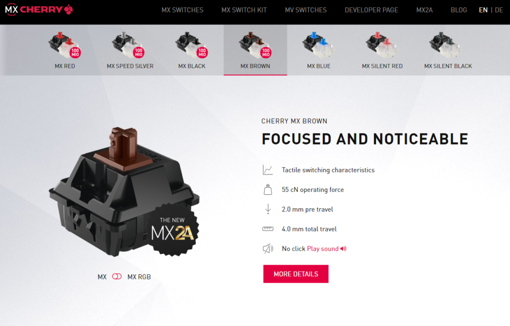
Obviously, the best key key switch choice for an Ultimate Keypad, these days, is to utilise Cherry MX key switches.
So, I designed an updated Keypad PCB for a Cherry MX key switch based Hexadecimal keypad.
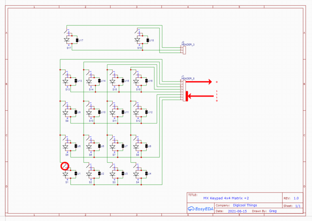
Here is the relatively straightforward schematic.

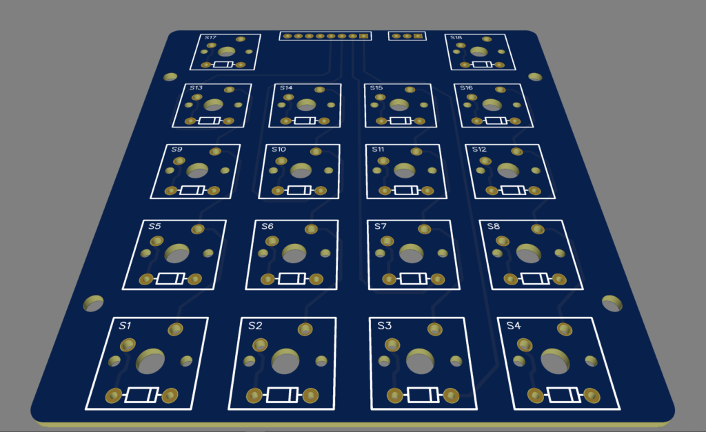
And, here is the resulting PCB layout.

The new design also allows for the optional use of key switch Diodes, if these are desired to allow for avoiding key ghosting, which can otherwise happen when multiple keys are simultaneously pressed.
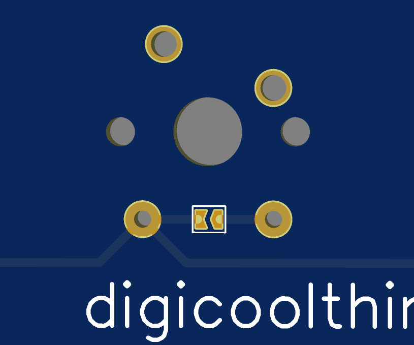
If Diode “key ghosting” protection is desired, you just need to install 1N4148 small signal diodes into the Cherry MX key switches.
If not required, then I have provided solder-bridge jumpers on the PCB, to allow easily circumventing the diode option.
Opening an MX key switch is very easy, when you have the right tool.

A diode can then be inserted through the 2 provided diode holes in the MX key switch body, and dropped into the body recess designed for this purpose.
The key switch then just clips back together.
Then, you now have 2 extra pins on your Cherry MX keyswitch, which are the legs or the diode.
Note that whether you choose to use diodes in your keyboard matrix also depends on your application, and the polling method that is used to read the keyboard matrix.
For example, to implement a diode protected keyboard matrix (assuming your input port pins are all pulled-high), the polling algorithm needs to pull each matrix row output low, one-at-a-time, and then detect for any depressed keys by identifying any column inputs that are pulled low (for the currently pulled-low row).
The diodes are effectively blocking any key ghosting occurring when multiple simultaneous key presses occur across different rows of the matrix.
The DREAM 6800 computer (which started me on this journey, as I explained in my first Hex Keypad video), however will not work with the diodes fitted.
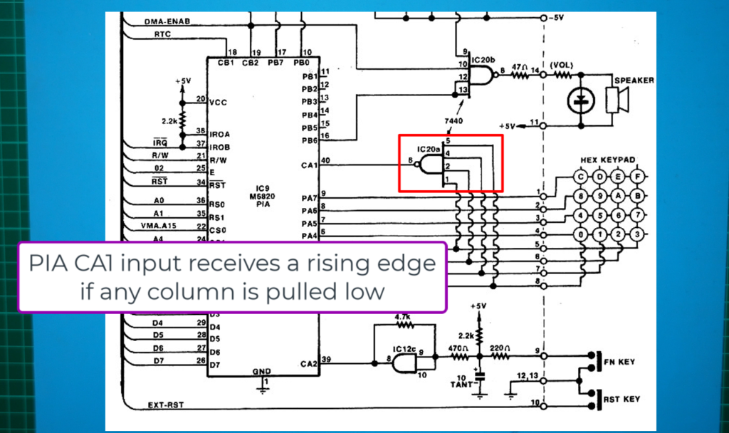
The DREAM 6800 CHIPOS ROM uses a clever approach of having all matrix rows pulled-low simultaneously, and via a quad input NAND gate triggers a rising edge PIA CA1 input when any column is pulled low, via a keypress.
When a low column is detected, the polling algorithm then reverses the keyboard port directions, so that all matrix columns are now pulled low, allowing the activated row to then also be determined.
This approach is quite efficient, but reversing the keyboard matrix column / row port direction is not compatible with a diode protected switch matrix!
My next challenge, to complete my Ultimate version keypad design, was organising appropriate MX Keycaps which have the desired Hexadecimal keypad legends.
The challenge is that readily available keyboard Keycaps can certainly provide for the A – F letters, but the numeric keys are generally designed for either the top row of a QWERTY keyboard, with punctuation symbols above the numbers, or, for a numeric keypad with additional arrow symbols etc.
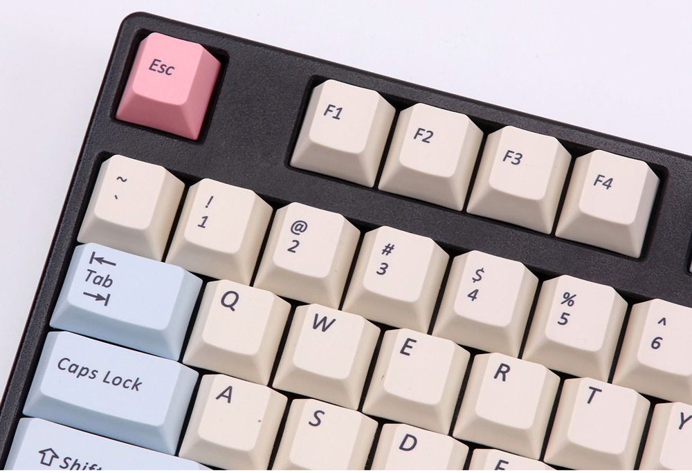

Neither of these readily available numeric keycaps are desired.
In fact, what we desire is simply just the symbols 0 – 9 and A – F, consistently sized and consistently located (eg. centred), on each keycap. We also want consistent legends for the two additional Reset and Function keys.
So, firstly, I located some MX Keycaps with clip-on transparent caps, which allowed printed legend sheets to be cut-out and inserted under the clip-on caps.
The clip-on transparent caps provided what initially seemed a viable solution.
But, I wasn’t particularly happy with the need to insert and align printed legends, and also the clip-on keycap style didn’t provide the desired MX keycap look & feel.
Next, I did some further research on the common MX Keycap profiles.
I arrived at the uniformly shaped XDA profile, as what I considered the most appropriate for a Retro Hexadecimal keypad.

So, next, I ordered some blank XDA profile MX keycaps, and set myself up with a Laser engraver, with the intent of using a low power engraver to burn black ink into the blank Keycaps, to make the desired key legends.

Some experimentation, including designing and making a jig to ensure consistent location of keycaps in the engraver, demonstrated that this approach held the promise of being successful.
Here’s an example of one of the keycaps I was experimenting with. There are multiple legends, as I was offsetting the legend so I could experiment 4 times on each keycap.

But, there were a couple of problems with this approach.
Firstly, making each keycap legend in the laser engraver was a relatively labour intensive process. First involving applying some black marker, then completing multiple passes in the laser engraver, and finally cleaning off the surplus marker ink to leave just the burned-in symbol.
Secondly, without some longer-term testing, I had no idea how robust the laser burnt legends would be, with the typical wear & tear of your fingers on the keypad, over a longer period of time.
This is where my Ultimate keypad design project stalled! That was a couple of years ago.
Then, recently, I revisited the project, inspired by a couple of things.
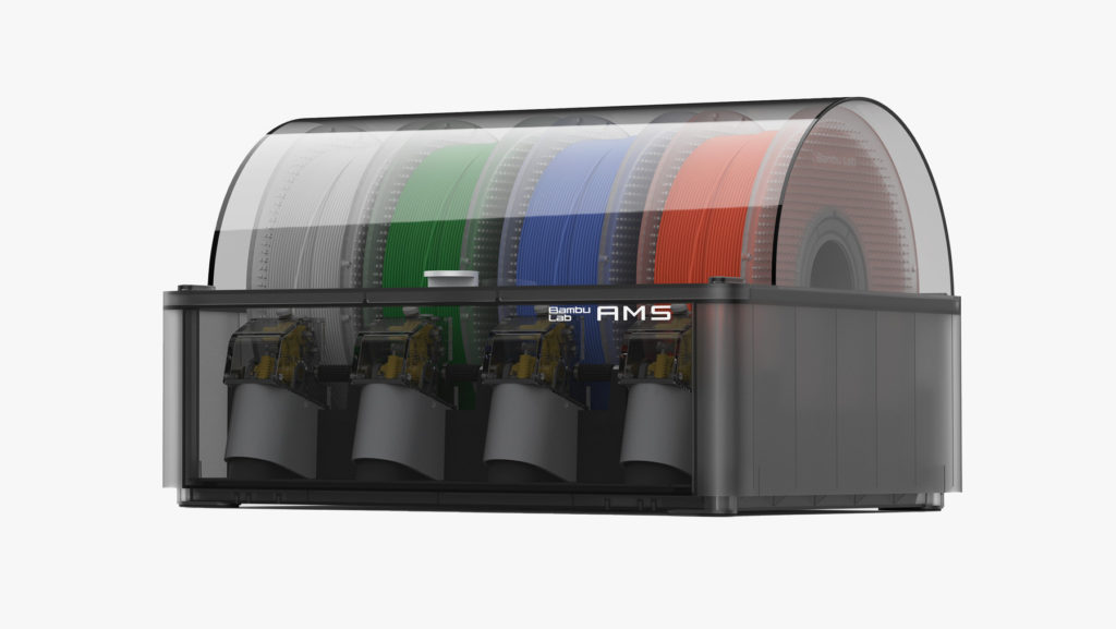
Firstly, I had since updated my 3D printer to a new Bambu Lab X1C with AMS, which was giving me some really good quality 3D print results. A level-up from my previous 3D printer.

Secondly, I noticed some, better than expected, 3D Printed keycap designs for a Commodore 64 keyboard, which someone had published on Thingiverse.
On test printing one of these keycaps, at a fine layer height, I was pleasantly surprised by the resulting 3D printed keycap quality.

The C64 Keycap test print on my new Bambu Lab X1C 3D printer was definitely a significant step up from when I last tried to 3D print a Cherry MX Keycap, just a couple of years ago.
Secondly, my Bambu Lab X1C came with an AMS, which allows easy multi-colour printing.
So, I had the idea of trying a two-colour print, to allow embedded legends (in a different colour), in the printed MX keycaps.
Inspired by this, I dived into creating my own XDA profile keycap models, from scratch, using Fusion 360.

I then created embedded text legends in the keycap models, and used Bambu Studio to colour-fill the legends with a different colour filament.
After numerous tweaks to perfect the Keycap 3D model, I have to say that I’m actually quite blown-away with the final result. Exceeding my previous expectations of what’s actually achievable with a FDM 3D printer.
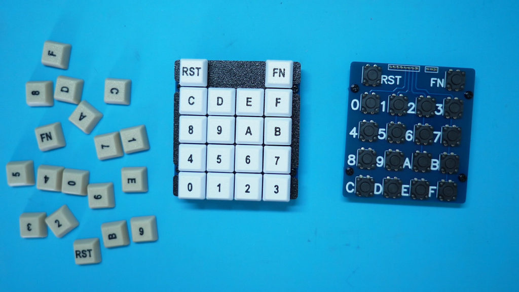
So here is a look at a finished set of Keycaps, fresh off the printer.
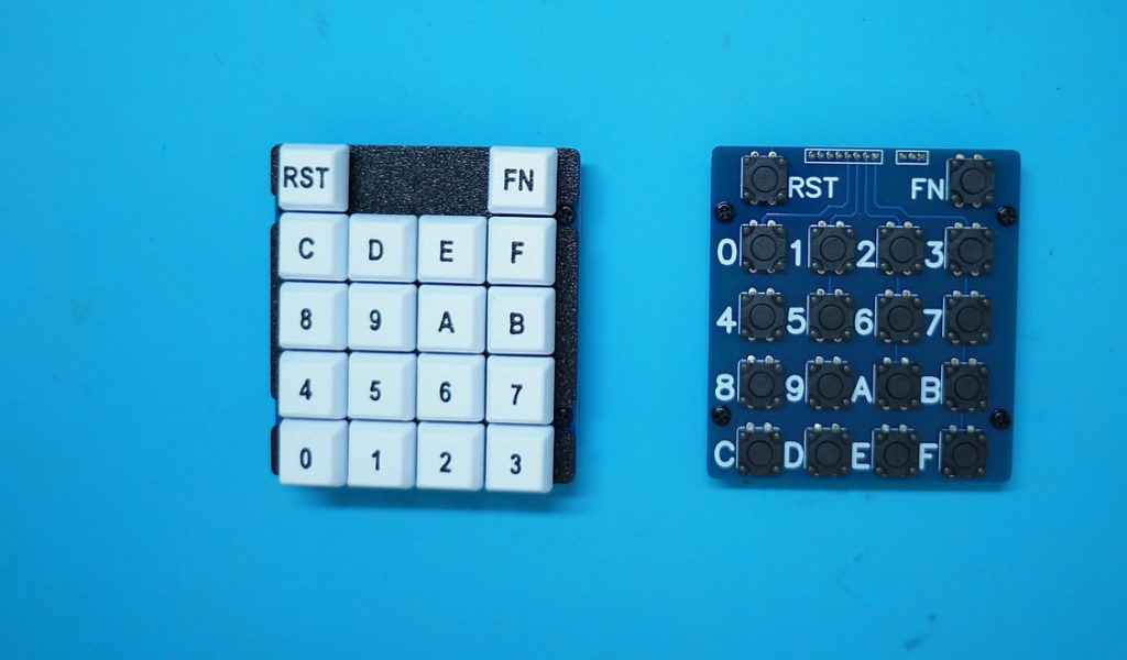
And, here is an assembled Ultimate version of my Hexadecimal Keypad.
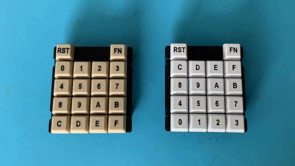
Initially I created the Keycaps in white with black legends, but in my desire to perfect the Retro look of the Keypad, I searched for the best “Retro Beige” colour that I could find, and I now also have Retro Beige keycaps with the same black embedded legends.
Here’s what the Retro Beige coloured key caps look like. I think they look great, and they also have a more “Retro” look to them, rather than the pristine white keys.
Also, after careful consideration, I choose the Cherry MX Brown Key switches as the most appropriate match for a “Retro” Hex Keypad. These are the non-Clicky Tactile-feedback style of Cherry MX key switch.
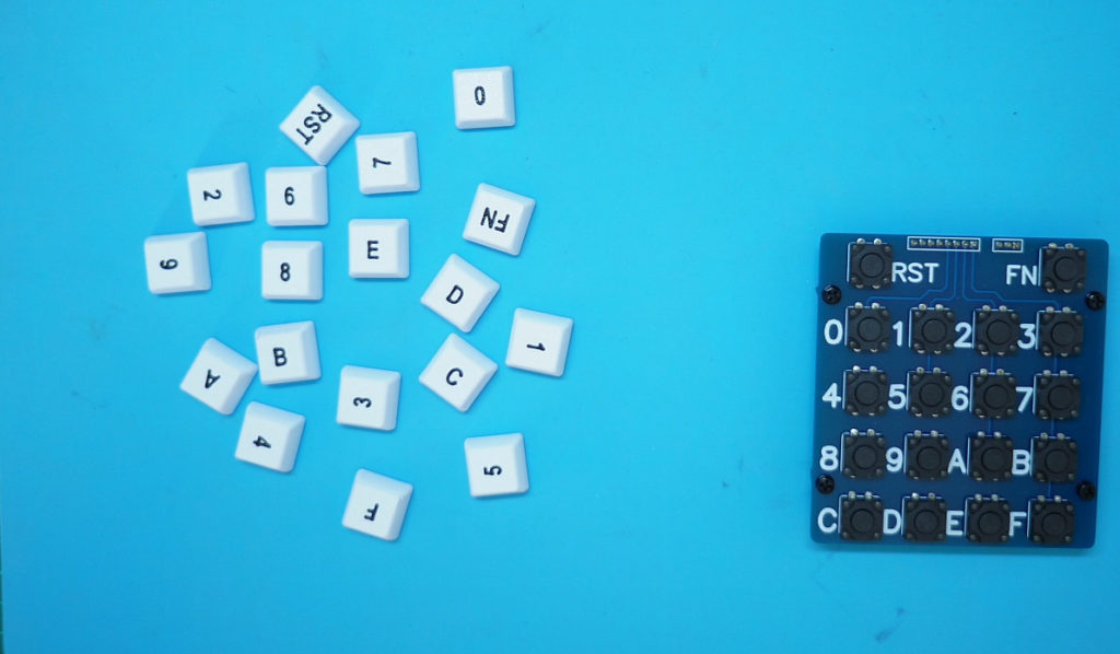
Finally, I’d note that the design flexibility of using Cherry Key switches for the hex keypad also extends to the keypad layout.
As we are using key caps, we can choose how we want the hexadecimal matrix to be laid out.
For example, you could choose to assign the key caps in the 0 – F order from the top, or, you could instead use a 0 – F order from the bottom of the keypad, or you might even prefer a numeric phone keypad layout, with the A – F keys around the edge.
You simply choose how you fit the key caps, depending on your preference or on the application.
The perfectionist in me is now happy enough with the result, that I have also added this Ultimate Hex Keypad to my Tindie Store, in Kitset form, for other enthusiasts who would also like a Cherry Key switch based Hexadecimal Keypad for their Retro computer project.
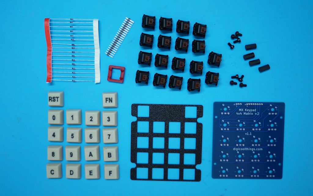
The Kitset will include all the parts to make the completed keypad, including the full set of dual colour 3D printed keycaps, the 3D printed key switch mounting plate, and also the optional 16x 1N4148 diodes, so you can choose whether or not you want to insert these into the supplied Cherry MX Key switches.
Also, the pin headers and the PCB stand-offs, to complete the Keypad.
In addition, I’m including the 3D printed Key switch opener, that I demonstrate in the video, to make installing the diodes easy (if you choose to use them).
Finally, there’s the choice of whether you want the White or the “Retro Beige” coloured keycaps, or alternatively, you can choose a bundle with both sets of keycap colours.
The video associated with this post also demonstrates the assembly of a Kitset.
To assemble the Kitset, first I solder in the pin headers. This includes an 8 pin header for the Hexadecimal matrix, and a 3 pin header for the Reset and Function keys.
Then, you’d fit the diodes in the key switches if you were taking the diode option. As demonstrated earlier in the video.
For my Kitset assembly I’m not using the diodes, so instead I solder-bridge the diode jumpers on the PCB, for each of the 16 hex key switches.
Note also, that the Reset and Function keys have pre-linked PCB jumpers, as you normally wouldn’t use diodes with these switches, as they’re not part of the matrix.
However, I included pre-linked jumpers for these two function keys, just in case you wanted to cut the PCB jumpers open and use diodes on these two switches.
Next, I fit the Cherry MX Key switches to the mounting plate.
After checking that all of of the key switch pins are nice & straight, the PCB should then just drop in place on the back of the key switches.
I then solder all the key switches to the PCB.
With all the soldering completed, I then fit the four PCB stand-offs.
Finally, I fit the keycaps, in the arrangement that I want.
And the Keypad assembly job is done!
I hope you enjoyed my Hexadecimal Keypad journey. If you have an application for your own Hex Keypad, and you’d like to support me, then please feel free to visit my Tindie Store.