
Although usage of the Digicool Things EPROM Programmer Adapter has been covered in other posts, and the reading of a Mask ROM and programming of an EPROM is also visually demonstrated in a YouTube video, I thought I’d add this post as a detailed written guide of the steps for successfully programming your EPROM.
However, in the first instance, if you haven’t yet viewed the demonstration video, I do strongly recommend that you first view the video in order to get a first hand demonstration of Adapter usage. You’ll find the video here:
If you’d like one of these Adapters, you’ll find a Kitset or a Fully Assembled & Tested option, on Tindie: https://www.tindie.com/stores/DigicoolThings/
Note: We no longer sell on eBay, as their high fees and forced mutiple exchange rate conversions (with exhorbitant fees), meant it was no longer financially viable to offer via eBay.
Programmer Preparation
Start up your TL866 Programmer application. At the time of writing, I’m using Xgpro v8.51 with my TL866II Plus Programmer. However, if you have the earlier model TL866A or TL866CS programmer then the Minipro application software is used (v6.85 at the time of writing).
In the [Select IC] panel you want to select the “AM27C4096” device. This is a 4Mb 16bit device that uses the JEDEC-approved 40pin DIP pin-out, which the Adapter uses to interface to the 27C400/800/160 and 27C322 devices.
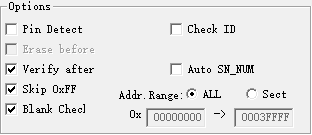
De-select the “Check ID” check-box in XgPro (or the “Device ID Check” check-box in the Minipro app). As we are not actually programming an AM27C4096 chip, the ID Check will not return the expected result.
De-select the “Pin Detect” check-box (only applies to Xgpro app). The Adapter circuitry that interfaces and switches between our actual target EPROM device means that an actual AM27C4096 Pin Detect test will of course not return the expected result.
Verify with the datasheet for your actual EPROM device, what the correct Vpp programming voltage etc. should be. You might consider this step optional, as the default voltages selected for the AM27C4096 have been just fine for all of the devices that I have programmed (so I just mention this for your awareness). eg. For a common STMicroElectronics M27C322 (32Mib EPROM) the Vpp is specified as 12v, however the Xgpro default 13.0v Vpp voltage has never caused me any issues.
Also optional, I do recommend selecting the “Blank Check” check-box option, as this makes the whole programming process a one click per bank exercise, with the blank check providing verification that we did remember to advance the bank select switch before attempting to program the next file segment.
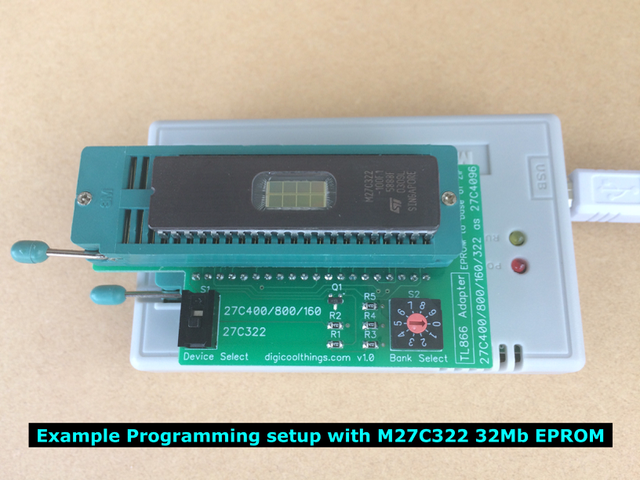
Insert and clamp the Adapter into the TL866’s 40pin ZIF socket, and then insert and clamp your blank EPROM chip (to be programmed) into the Adpater’s 48pin ZIF socket. Take special note that the EPROM is positioned to the base of the ZIF socket, as is noted on the PCB (refer photo below for correct chip positioning).
Finally, check that the Adapter’s “Device Select” switch is in the correct position (matching the inserted EPROM device), and it’s also a good time to verify the “Bank Select” rotary switch is set to the initial Bank 0 position.
The Bank Select Switch Pointer
The above photo shows the original v1.0 Adapter, which used a flush “screwdriver only” Bank Select switch. This flush switch had a clear arrow to indicate the position selected.
The later Adapters (v1.1 and up) implemented an improved shaft & slot Bank Select switch, to allow simple bank switching with just your fingers (screwdriver optional!).
This improved finger selectable shaft & slot switch indicates the selected position via a vertical groove / channel, which runs down one side of the shaft (from one end of the slot across the top of the shaft). This can be seen in the close-up photo below.
Once you see the groove down the side of the shaft it will be plainly obvious, however I’ve added this note to clarify. One first time user was initially confused by a quite prominent plastic molding “dot” visible on the top of the shaft.
So, in summary: For v1.1 and up, the switch position pointer is indicated by the groove in the shaft, not by the plastic molding “dot” on the top of the shaft.

ROM Image File Preparation
If you are directly duplicating an existing Mask ROM chip, then the following steps in this section will not apply. This is because the process of reading a Mask ROM chip (using the Adapter), will give you the 512KiB file segment(s), exactly as you need them in order to program them back into your replacement EPROM.
If however you have been provided with (or have downloaded) a single binary ROM image file, that you need to program into your EPROM, then there are a couple of preparation steps you need to perform.
Firstly, you need to ensure the binary file is in the correct endian byte order. As we are dealing with 16bit EPROMs, you need to consider the big-endian versus little-endian byte order.
If you have downloaded a ROM image, then the 16bit word “byte pairs” may have been swapped from the endianness ROM byte order that is expected by the original hardware device.
If you’d like to know more about this potential byte order issue, I suggest this Wikipedia article: https://en.wikipedia.org/wiki/Endianness
If a byte swap is required, I find the easiest way to fix ROM image file endianness is to download the free GQ-4X Programmer software (GQUSBProg), which has a useful “Buffer Byte Swap” command.
ie. (1) Open your full binary ROM image file in GQUSBProg. (2) Select “Buffer Byte Swap” command. (3) Save file to a new byte swapped file (to use for your TL866 programming).
If programming a 27C400 (4Mib) you are now ready to go. However, for the larger devices you’ll next need to use a file split utility to split your single large EPROM binary file into separate 4Mib (512KiB) segments. This is required because the TL866 thinks you are programming 4Mib EPROMs (ie. 27C4096).
For this purpose I use a free utility called HJSplit, which has a very simple interface to allow creating multiple numbered 512KiB file segments from your larger binary file.
Note: At the time of writing, the HJSplit utility appears to be no longer available for download. One alternative I found is GSplit. GSplit is also free, however it is a more comprehensive utility, which needs some setup in order to get it to just do a simple binary file split. eg. You need to select “Do not add GSplit tags to piece files”, in order to just get the raw binary file segments that you want. Of course, Google is your friend here, so feel free to look for other file split alternatives (if HJSplit is unavailable).
Remember, what you need are one or more 512KiB binary files. To avoid confusion, these are 524,288 byte file segments. Be aware, depending on your OS / file manager, these files may appear as 524KB (based on 1000’s, instead of the true 512KiB).
Programming your 27C400/800/160/322 EPROM
With your programmer now setup, and your ROM image file prepared, you then proceed to program & verify each 512KB file segment, using the Adapter’s “Bank Select” switch as follows:
- 27C400 – Single 512KB file, no Bank Select required!
- 27C800 – Two 512KB file segments, use Bank Select 0/1
- 27C160 – Four 512KB file segments, use Bank Select 0/1/2/3
- 27C322 – Eight 512KB file segments, use Bank Select 0/1/2/3/4/5/6/7
Troubleshooting
If, by this stage, you haven’t successfully programmed your EPROM, here are a few suggested points for you to check which might assist you with identifying the problem:
- Have you installed the lastest version software application for your Minipro (TL866A/CS) or XgPro (TL866II Plus)?
- The 27C4096 device is selected? (eg. AM27C4096)
- “Check ID” is unselected (although this will just give an: ID Error!).
- “Pin Detect” is unselected? (XgPro only).
- The Adapter “Device Select” switch is in the correct position for the EPROM type inserted.
- The Adapter “Bank Select” switch is in the correct position for each file segment being programmed (note the switch is zero based, but your file splitting software may have used 1 based file segment numbering).
- EPROM chip is inserted to the base of ZIF socket (ZIF pins 1-3, 46-48 unused for 42 pin EPROM).
- EPROM is inserted the correct way around (IC notch / pin 1 is towards the top / ZIF lever end).
- Binary ROM image file is in the correct endianness (Does the byte order need to be swapped?).
Hopefully this usage guide has been helpful, or useful as a reference. Of course, once again, I do recommend that the easiest way to quickly get up to speed with Adapter usage is by watching the Youtube demonstration video (linked at the top of this post).
“One first time user was initially confused by a quite prominent plastic molding “dot” visible on the top of the shaft.”
It´s me
hahahaha
Once again, thank you very much for the clarification. =)
Thanks, but I believe it’s actually a Thank You, to you!
I believe it was probably your question that prompted me to put together this indepth written “Usage Guide” post.
Hopefully it has provided a good reference for everyone using the Adapter. 🙂
Just wanted to inform You, that i successfully used a v1.2 adapter with the more recent T56 ROM programmer with an AM27C800 EPROM (AM27C400 is natively supported by T56).
It worked like a charm, thank you so much again for this wonderful little board.
I wish you all the best and health in these times. 🙂
Thank you for the report that the Adapter is also compatible with the newer T56 Programmer. I haven’t obtained a T56 as yet, as I have yet to have a requirement to justify the expense.
Given the step-up in price for the T56 it is at least good to see that the more “hobbiest wallet” friendly TL866II Plus remains in production!
Take care and stay safe.
Thanks for the article a lot.
I just checked and 27c400 is marked as natively supported by tl866II plus.
Are you sure adapter is need for that programmer? Can someone help please.
Hi. Unfortunately the 27C400 is not natively supported by the TL866II Plus.
An Adapter is still needed. As is also needed for the 42pin 27C800, 27C160, and 27C322 devices from the same Retro 16bit Mask ROM pin-out compatible family.
If you want to check again, the latest TL866II Plus Universal Programmer Device Support List can be found here:
http://www.xgecu.com/MiniPro/TL866II_List.txt
Perhaps your “27C400” search found the different 27C4000, 27C4001 supported devices? (which are non-compatible 32pin 8bit wide EPROM’s).
Hope this helps.
oh dear, yes you are right. My bad.
Thank you very much for clarification!
Can you tell if it is possible to use the MX29F1615 chip with it? Looking at the datasheet, it is very similar to the 27c160.
Hi. I’ve not used the MX29F1615 FLASH EEPROM, but I do see it’s pin compatible with the 27C160 EPROM, and appears to be EPROM Read compatible (so can be used in place of the 27C160).
You should therefore be able to use the Adapter to Read / Dump an existing MX29F1615 device.
However, Programming is another mater. As it is a FLASH EEPROM, you would need to determine if there is a 27C4096 pin-out compatible FLASH EEPROM, that the TL866 Programmer supports, and that is also compatible with the MX29F1615 JEDEC-standard EEPROM commands.
If such a device exists, the you should then be able to also use the Adapter to program the MX29F1615 in Page Erase / Program mode.
I did do a quick Google, but I didn’t locate a 27C4096 pin-out compatible FLASH EEPROM device. You may have better luck?