
This journey started when I rediscovered my Sega Master System II, which had been buried in a wardrobe for many years.
With over 20 years video & home theatre experience, I immediately recognised the need to improve the quality of the console’s video output. Necessary to fully enjoy, and best re-experience, the amazing gameplay offered by retro gaming.
Having experience in electronics design, and with perfectionist tendencies, I was less than impressed with the various Sega console mods discussed and documented online.
It was therefore inevitable that I needed to take a clean sheet of paper, and design my own optimal solution.
The below summarises the (achieved) design goals:
- Pixel sharp image quality via S-VIDEO output.
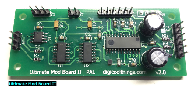
- Professional quality surface mount IC based “Mod” circuit board.
- Fully buffered video output signals, with correct output levels and impedance.
- High Quality S-VIDEO / Composite / Dual Audio outputs.
- Smart 50Hz / 60Hz mode switching via existing Console Button (Pause / Reset).
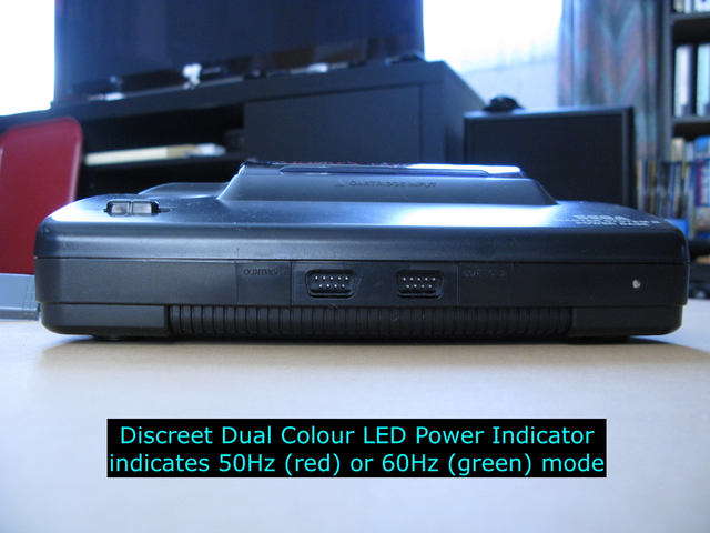
- Dual colour LED power indicator indicates 50Hz / 60Hz mode.
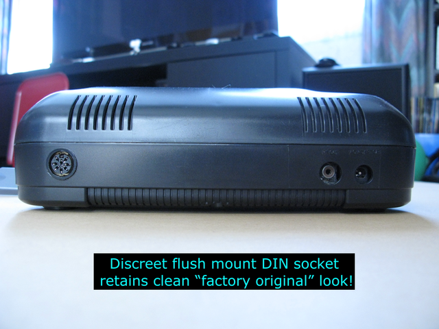
- Discreet flush mount professional DIN socket to retain a clean factory original look.
- High Quality Dual Use S-VIDEO / Composite / Dual Audio cable, with shielded metal plug.

Read on to understand the journey that delivered the “Ultimate Mod Board II”.
Seeking the Optimal Video Quality
If you are experienced in working with Standard Definition (SD) Video, you’ll know that the optimal picture quality is obtained by using a “component” video signal source.
Specifically, a “component” video signal that has maintained signal separation, from the source, between the brightness (luminance), and the colour (chrominance) signal components.
Combining these picture signal components into a single “Composite Video” inevitably creates horrible visual image artefacts, which significantly degrade the quality of the rendered video image.
It is fair to say that Composite Video is a compromise. It could be said to exist due to historic requirements for a single combined analog video signal. eg. To allow analog broadcast (transmission) on a RF modulated (VHF/UHF) carrier.
Obviously, if we have a locally generated video source (as in the case of a Game Console), and we’re therefore not dealing with a broadcast video signal, you simply DO NOT want to utilise a Composite Video signal, if you are seeking optimal video quality!
“Component” Video Options
Separated (“component”) video options vary, however the common standards are:
- RGB (+ Sync) – Provides three seperate luminance signals, one for each primary colour (Red, Green and Blue).
- Component (YPbPr) – A single luminance signal, separated from two “colour difference” signals.
- S-Video – A single luminance signal, separated from a single chrominance signal.
Although I’ve listed the above common standards in descending order of their bandwidth capability (ie. optimal picture quality potential), any one of these “component” video options provides a startlingly significant picture quality improvement over a Composite Video signal.
Indeed, for retro gaming console video bandwidth requirements, any one of these common standards is fully capable of rendering the optimal video quality.
In fact, most people wouldn’t perceive any visible difference (of any significance), between these common standards when viewing a retro gaming console’s output. Whereas, you can immediately see the significant picture quality improvement provided by any one of these component video options, when compared to the nasty image artefacts visible in a Composite Video signal.
Which Optimal Video option?
The answer to the question of which component video option is best, for our optimal retro gaming console experience, can be determined by identifying the best compatibility with the display connectivity standards in your locale.
In simplest terms, this can perhaps be translated to whether or not you are based in Europe.
In Europe, a common SDTV connection standard was the EuroSCART connector. This connector provided Composite Video input, often along with RGB(S), and sometimes also supporting S-Video input on the SCART connector.
For the rest of the word, the common SDTV connection standard was an RCA Composite Video connector, with the optimal input being the 4 pin ”mini-DIN” S-Video connector.
In my part of the world (New Zealand / Australia), the S-Video “component” video connection standard was, and remains, the optimal Video connection option for SDTV standard input (eg. Retro gaming consoles).
While Composite Video may have been considered acceptable to view on an old (eg. pre-Y2K) 29 inch, or smaller, analog CRT television, most modern large screen flat panel digital technology TV’s only further emphasise the nasty image artefacts, and poor quality, of a Composite Video signal.
My partner made the issue very clear when she mentioned that she couldn’t look at our console’s Composite Video picture for very long (from our normal 1m – 2m playing distance), as she was developing a headache from the large screen blurry images. However, since changing over to a sharp S-Video connection, she can now enjoy large screen retro gaming!
One other point to note is that, although many modern TV’s have Component (YPbPr) inputs, there is often compatibility problems with SDTV input from gaming consoles. Component (YPbPr) inputs tend to be fully compatible with HDTV signal standards (eg. 720p / 1080i), but often less so with retro game console SDTV sources.
In summary, the “Optimal Video” option is clearly S-Video, assuming of course your display has a S-Video connection. In fact, I would go further and say that to fully enjoy today’s Retro Console Gaming absolutely requires an S-Video connection (unless of course you live in Europe and are instead already using a RGB EuroSCART solution).
What’s wrong with the commonly discussed Sega mods?
Some retro gaming consoles, like the Sega Master System, provide only RF modulated outputs.
Some later retro consoles, like the Sega Mega Drive / Genesis, provide only Composite Video and RGB signals on their A/V connector.
Many of the commonly discussed Sega Master System console mods focus on providing just a “Composite Video” output, to resolve the connection dilemma caused by the absence of analog RF tuners in modern TV’s.
The SMS mods that do provide for an S-Video output are commonly implemented with a simple capacitor & resistor addition, which I’d refer to as a “cheat” bodge. It’s an attempt to provide a S-Video compliant output that, at best, approximates the correct signal levels. This results in a signal impedance mis-match with image degradation commonly observed, often with incorrect colour rendering.
For this reason, I was somewhat less than impressed, so I started work on a design for my own SMS “Ultimate Mod Board”.
Sega Master System II “Ultimate Mod Board” (Version 1)
It’s noted that the Video Encoder design in the Sega Master System does not provide the correct S-Video signal levels (it was early days for the S-Video standard). I therefore decided that a “Mod” circuit design which more correctly adjusted the signal level, and then appropriately provided video buffering of the video outputs (for correct output impedance), was a much more correct solution.
As this approach involves more circuitry than just the common capacitor & resistor “cheat” bodge, I also wanted to design a professional printed circuit board (PCB), to create a more robust and reliable “professionally built” solution.

A further common Sega Master System “Mod” is to install a switch to allow changing the video output between 50Hz and 60Hz. As you may already know, this is quite an important Mod for PAL SMS consoles, as many games were originally written for the NTSC (eg. USA) market, and were therefore optimised for 60Hz gameplay. When these titles were released, unchanged, into the PAL (50Hz) market, the resulting gameplay is slowed down (slower than the designer intended), with slowed down sound (pitch changed), and also a reduced screen display area (larger screen borders).
Typical 50Hz / 60Hz switching “Mods” involve installing an ugly manual toggle switch, sticking out the back of the console.
The perfectionist inside me was also seeking a console “Mod” solution which would retain a “factory original” look to the console. I really abhorred seeing pictures of modified SMS consoles with an ugly toggle switch. Not only that, also a poorly aligned row of RCA sockets added, to provide the Composite Video + Audio output mod. Nasty, but more on that later!
To further live up to the “Ultimate Mod Board” name, I decided to design and program a micro-controller based circuit to allow a re-purposing of the existing SMS “Pause” button, to now be a multi-function “Mode Change” and “Pause” switch. The implementation to also include the non-volatile memory storage of the current mode, so that the currently selected 50Hz / 60Hz setting is retained through power off/on.
One further common SMS “Mod” is to add the missing Power LED, to provide a visual indication of the SMS being power on. To round out the “Ultimate Mod Board” design a dual-colour Power LED is implemented, allowing the LED to also provide an indicator of whether the SMS is set to 50Hz or 60Hz mode.
The final perfectionist component of an “Ultimate Mod Board” modified Sega Master System is to ensure a professional “original factory look”. Specifically, without a nasty row of added RCA sockets etc. which simply ruins the beautiful design of the original SMS console.
In addition to retaining an original look, we want to provide a high quality cabled connection to your TV, to support the optimal signal quality and to also ensure a robust connection.
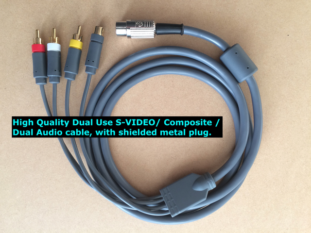
For this, a high quality shielded metal DIN connector based “S-Video / Composite Video / Dual Audio Lead” is supplied, along with an appropriate black “colour matched” flush mount DIN socket unobtrusively installed in the back of the console.
Finally, the perfectionist inside me is satisfied! I’m now able to enjoy my “Ultimate Mod Board” modified Sega Master System, with beautiful and insanely sharp graphics on my 50” flat panel display, and also play selected games at the 60Hz speed they were intended to be played at!
And Finally… The creation of “Ultimate Mod Board II”
OK, so this story is not over yet. I was then introduced to the Sega Mega Drive (II), and the perfectionist in me was once again… not fully satisfied!
This Sega Mega Drive (SMD) introduction came about due to a question I was asked: Do I have the same “Mod” available for a Sega Mega Drive? As I’d never owned a SMD, the answer (at that time) was of course: Unfortunately not.
But, this question had now triggered a personal desire to investigate further. So, I purchased a Sega Mega Drive II, and proceeded to pull it to pieces and analyse the circuitry.
Fitting my existing “Ultimate Mod Board” to the Sega Mega Drive actually worked, and provided a nice sharp S-Video output… up to a point. When testing the 50Hz / 60Hz switching I discovered I had a B&W picture at 60Hz (colour was lost).
Further investigation confirmed that the SMD Sega chip now switches the colour sub-carrier clock divider, when you switch modes. Rather obviously, as the relevant pin is labelled NTSC / PAL selection! Google quickly informed me that resolving this issue is commonly referred to as the SMD “PAL Colour Fix” or “60Hz Colour Fix” Mod.
OK, as the additional circuitry required to resolve this clock divider issue would require a new PCB design, I was inspired to think beyond my existing “Ultimate Mod Board”. To ask myself the question: How can I improve on the existing design and create a worthy “Ultimate Mod Board II”?
I had to be brutally honest with myself, and admit that the perfectionist inside me was never completely 100% satisfied with the requirement for the “adjusted signal level” aspect of the design.
So, with the combined goal of both: 1. Satisfying the perfectionist in me, once and for all, and 2. Designing an “ultimate” Ultimate Mod Board, which would also provide a single optimal solution for both SMS & SMD consoles, I pulled out a fresh “clean sheet of paper” and got started designing.
The obvious solution was to replace the entire original early 90’s video encoder section of the Sega circuit with an improved & modern standards compliant Video Encoder circuit. In addition to ensuring the best possible image quality and colour accuracy, this approach also ensured that any tired components (in the old video output stages) are, by design, being replaced with new parts.
An addition benefit of this approach is that this new comprehensive “Mod” board design can also be used to cleanly repair any Sega console which has had a failure in it’s video output circuitry.
The new design essentially takes the raw RGB output from the Sega chip itself, and replaces all of the existing Video Encoder / Video Output circuitry with a new updated design using new components. Nice!
“Ultimate Mod Board II” – Perfectionist Satisfied!
The design implements it’s own PAL colour sub-carrier clock divider, so the SMD 60Hz colour issue is resolved. Also, by completely replacing the Colour Encoder with a more modern standards compliant Colour Encoder circuit my perfectionist niggle is resolved, by completely avoiding the “adjusted signal level” aspect of the earlier design.
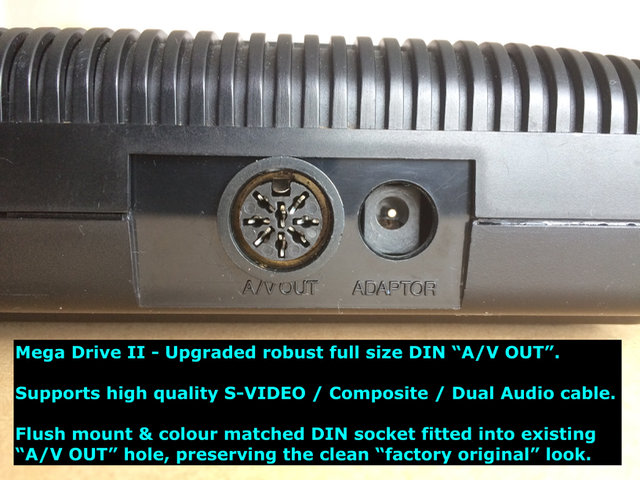
To round out this story, the original design of the Sega Mega Drive II console case allows for a very effective and professional “factory original” look, Ultimate Mod Board II installation. Even better than the very clean Sega Master System II installation, the SMD requires no new holes to be drilled in it’s beautiful case!
There is also a further added benefit obtained, by replacing the original (often very tired) Mini-DIN A/V connector, with a significantly more robust (and brand new) full size DIN flush mount connector. Exactly the same socket as was utilised with the original “Ultimate Mod Board” SMS installation. I’ve found that SMD Mini-DIN A/V connector sockets become troublesome or have simply just worn-out after years of use.
Achieving this A/V connector upgrade does require the removal of the original old PCB mounted mini-DIN connector (appropriate, as it is no longer needed), however the benefit is that a new case hole is not required. Also, the existing factory “A/V” labelling on the case remains below the new socket. Nice!
Finally, for the SMD there is of course no “Pause” button. Instead, the “Reset” button is re-purposed as a multi-function “Mode Change” / “Reset” switch. This works perfectly. As with the original design, the “Reset” signal is only passed through if the switch is pushed momentarily (less than 1 second). Therefore, by holding down the “Reset” switch until the Power light changes colour (indicating the mode change), no reset signal is sent / the game is not reset.
Thanks for reading the full story of my “Ultimate Mod Board II”. I hope you enjoyed the journey.