
I’m now finalising the design of my first I/O Card for the Minimalist Europe Card Bus (MECB).
I need a driver circuit for a single connection to an Interrupt input on the Bus, so I thought I’d look at some options for connecting a positive logic signal to the active low Interrupt input on our retro TTL level system Bus.
Join me as I compare the traditional 7406 Open Collector Hex Invertor solution, to some more compact and less wasteful solutions.
The Interrupt inputs on the Minimalist Europe Card Bus and our CPU card, trigger initiating an Interrupt Service Routine on the processor, either during a negative transition, or, when a low level is applied to the relevant Interrupt input.
On the Minimalist Europe Card Bus we bring out both the common Maskable Interrupt input (INT, or IRQ), as well as the Non-Maskable Interrupt input (NMI).
As a processor Interrupt signal can originate from multiple sources, it’s normal for Interrupt request bus signals to be pulled high with a pull-up resister at the CPU. Any connection to the Interrupt input is then only made via either an Open Collector or an Open Drain driver.
i.e. You never drive the Interrupt input signal high!
This avoids any conflict with other devices that are also connected to the Interrupt input.
Connecting a positive logic signal to the active low Interrupt input on a retro TTL level system commonly involves the use of devices like the TTL 7405 or 7406 Hex Inverter chip, which have Open Collector outputs.
The 14 pin TTL 7406 is actually a very nice self-contained solution, and was commonly used.

However, if you only have a requirement for one or two Interrupt connections on your peripheral Card, and you have no other need for an Inverter, then using a 14 pin Hex Inverter chip is rather wasteful of both PCB space and of unused Inverter gates.
This is the case with the Minimalist Europe Card Bus I/O Card that I’m currently designing.
I only need a single optional Non-maskable Interrupt connection, which is to be driven from the positive logic output of a programmable timer. The “optional” part is easily taken care of with a jumper.
I also have no need for any additional inverters. So, implementing a 7406 Open Collector Hex Inverter, just for this application, would be quite wasteful.
Also, although there are plenty of single gate SMD solutions available, in keeping with the Retro theme I’m ruling out the use of any SMD devices for my Retro designs.
My first thought was to implement a single transistor inverter, using a common cheap TO92 small signal NPN transistor.
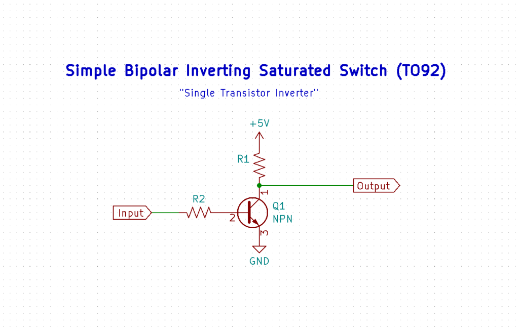
But, this does really require a current limiting resistor on the base connection, and although switching time is plenty fast enough, such a circuit can suffer from a slow turn-off rise-time which can limit achievable Interrupt frequency.
Rise time can be resolved with a second transistor (and more resistors) in a Schmitt trigger arrangement, but again we are adding more components. For this reason I’ll rule this option out.
The next device I’m considering is the useful SN7545x series of 8 pin Dual Peripheral driver chips, which I also have available in my parts drawers.
These compact 8 pin chips provide two TTL logic level gates with Open Collector driver outputs.
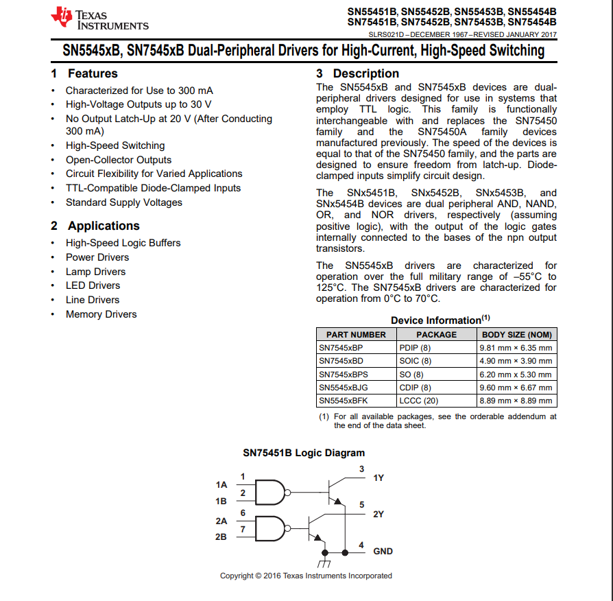
The SN754x chips are good for driving up to 30 volt / 300ma loads, but are also just as useful as a physically smaller 7406 replacement, when no more than two Open Collector drivers are needed.
So, using a SN7545x chip instead of a 7406, would at least satisfy the goal of something physically smaller, and with no additional components required. Although, it’s still wasteful of a gate, as we only need one of the two available gates. But this option is still worth having a look at, for comparison purposes.
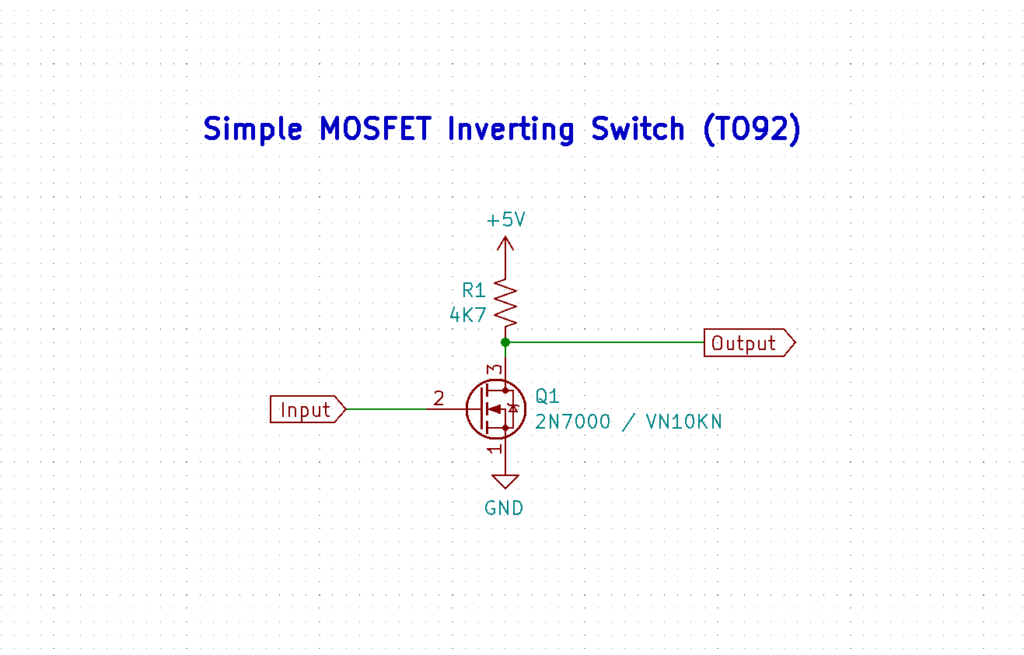
Finally, there is the thought of implementing a traditional single transistor inverter, but using a cheap TO92 packaged low power MOSFET instead of a BJT. Using a FET has the benefit of not requiring any current limiting resistor (on its gate input), and potentially providing a faster OFF recovery time than a BJT solution.
Of course, as usual, a simple test will tell us if this is a good option.
I have some VN10K in my parts drawers. These are N-Channel TO92 packaged devices, which are likely well matched to the job.

But, to start of with, I wired-up the traditional 7406 Hex Inverter on a breadboard, so we could measure how it performs, to set the benchmark of how a TTL 7406 responds in our breadboard environment, with an appropriate pull-up resistor.

I used the Baud Rate Generator test circuit (which I had wired-up in my last post / video), which I still had on my breadboard. This provides a good variety of square waves to choose from, for testing with.
I’ll use the 307.2kHz ouput for these driver tests.

Firing this circuit up, we can view the resulting traces on our Oscilloscope.

On the trace you can see the input to the 7406 buffer in yellow, edge triggered on the low transition at 800mv.
The Open Collector output is shown on the purple trace.
Interestingly, although we can see a nice fast trailing edge on the Inverter output, as the Open Collector output switches on, we are seeing a relatively slow recovery from Low to High, of just over 500ns (based on a safe 2.4V TTL High level threshold), when the Open Collector output is switched off.
Now this slow rise time will definitely be impacted by the added capacitance of our breadboard circuit, but it also draws my attention to the fact that I’ve initially used a 10K ohm Resistor Bank for the Interrupt pull-ups on my CPU card, so this first scope trace is based on a 10K pull-up.
I had used 10K pull-ups on the CPU Card, simply as I had plenty of these in-stock, as they’re commonly used as the pull-up value when working with modern microcontrollers etc.
But, I do remember having the earlier thought, that back in the TTL days of the 80’s a value of 4.7K was always the go-to value for TTL logic family pull-ups.
So, let’s swap out our 10K pull-up, for a 4.7K pull-up, just to see how it impacts the rise time.

As expected, a quite significant improvement from the over 500ns, to now just over 200ns.
With double the current available and a lower voltage drop across the pull-up resistance, it obviously helps with pulling the level back up a little quicker, when the open collector driver is turned off.
Now I know the added breadboard capacitance will be playing a part in this, but even so I’m going to re-visit the CPU Card schematic and update the CPU input pull-up Resistor Bank to specify 4.7K, instead of 10K.
Even just because my past experience with TTL tells me this is the right thing to do!
Okay, so with the 7406 measured, to set our benchmark breadboard circuit, let’s now take the 7406 out of the breadboard, and instead wire-up an 8 pin SN75452 dual gate Open Collector driver IC.

I’ll stick with the 4.7K pull-up on the output, on the basis that a 4.7K pull-up Resistor Bank is now implemented on the CPU Card.
With this circuit now implemented on our breadboard, let’s again look at the resulting scope trace.

As I expected, compared to our 7406 benchmark circuit, this 8 pin IC option looks to be performing well.
Finally, let’s now try out a VN10K TO92 MOSFET, to see what it delivers.
Here is the schematic of the simple MOSFET test circuit, that I also drew-up.
With this circuit implemented on our breadboard, let’s again look at the resulting scope trace.
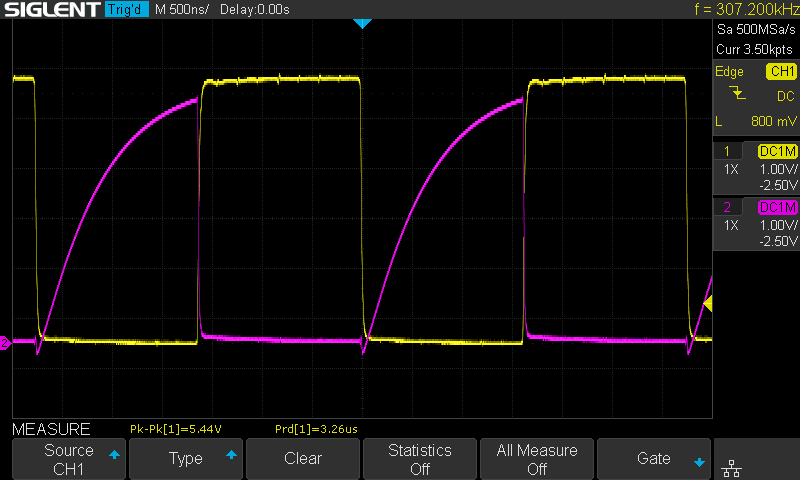
Okay, so this simple and compact single TO92 device solution is looking good. We can see a nice fast trailing edge when the FET turns on, and we are seeing a comfortable recovery time when the FET turns off, which looks fine when compared to our 7406 benchmark.
The behaviour in fact looks very similar to the SN75452 option.
In summary…
I think our low power TO92 MOSFET option looks like the simple and compact “Retro friendly” solution that I’m after for my current need of a single Interrupt line driver, and no requirement for any additional inverter gates in the design.
However, it is also worth making a note that the 8 pin Dual In-line Package SN75452 looks like a good option when an application requires two Open Collector drivers in the design, or when an application would benefit from having a 2 input gate controlled Open Collector driver. Noting that the SN7545x family provides devices with either AND, NAND, OR, NOR for the 2 input gate control of each Open Collector output.
With the ideal Interrupt driver option selected, I’m now ready to finalise my I/O Card design and get some prototype PCB’s ordered!