
While considering my next CPU card design, I decided to first take a look at the Reset circuit design.
My first MECB CPU card faithfully used the same “old school” reset circuit design, as we’d used in the early days. That is, a capacitor, two resistors, and a Schmitt triggered input chip.
Now, there’s nothing wrong with that, but I figured there’s probably a tidier “Retro friendly” solution these days.
Join me, as I present and then test the operation of a “Microprocessor Monitor” based alternative solution.
Requirements
My requirements for an alternative Retro CPU Reset solution were pretty simple:
- It had to still be “Retro friendly”. Specifically, no surface mount devices! Purely through-hole.
- It had to be cheap. So, maybe a $1 component cost, at the most.
As it turns out, I was pretty happy with what I found.
Microprocessor Monitor
After researching a few options, what I eventually found is the MicroChip TC1232 “Microprocessor Monitor”.
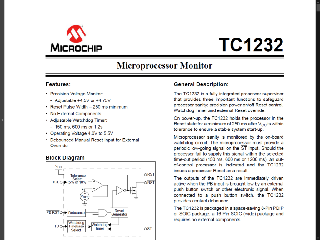
This little chip basically provides a power-on reset, support for debouncing a manual reset button, and also a watchdog timer facility.
Although I don’t currently need a watchdog timer, it’s a good feature to have available, especially if I was to use the same reset solution for other projects.
But, what I really liked is that this chip does all of this, with “No External Components” required, and it’s also available in a “Retro friendly” 8-pin Dual In-line Package.
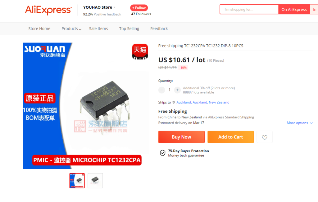
To complete my short requirements list, I also found I could buy 10 for about $10, including shipping, from AliExpress. So this also satisfied my $1 component cost limit.
So, I then created a quick Schematic comparison between the original Schmitt trigger based Reset circuit, that I’d used on my existing 6809 CPU card, and an alternate reset circuit based on the TC1232 chip.
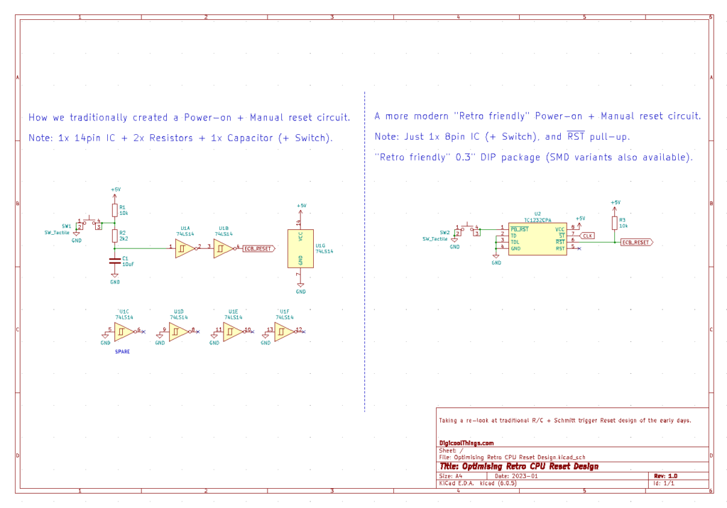
As you can see, the existing “old school” circuit uses a 14-pin Schmitt trigger input 7414 based hex inverter chip, along with a capacitor and a couple of resistors. All of this obviously consumes more PCB space than the single 8-pin DIP package TC1232 solution.
In addition, as I said earlier, I really liked the claim on the datasheet, that “No External Components” are required.
This would’ve been a huge attraction back in my early wire-wrap days, when the need to add additional discrete components usually meant adding an IC header to a wire-wrap IC socket, to hold and allow wire-wrapping in additional discrete components.
So it looks like for a TC1232 based Retro CPU reset solution, we just need the 8-pin chip and our reset button. Awesome.
A Couple of Things to Note
Now there are a couple of things to note.
Firstly, we need to ensure the TC1232’s watchdog timer is constantly reset, to avoid undesired system Resets.
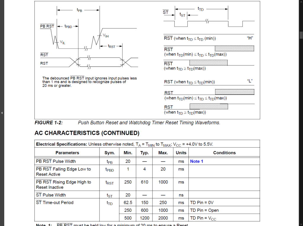
This is controlled by the Strobe input pin, which requires a falling edge to reset the timer, at least once every 150ms.
Fortunately, the datasheet tells us that the minimum pulse width for the Strobe input is 20ns.
If we were to use a clock signal to reset the watchdog timer, this would equate to a maximum frequency of around 25Mhz (based on a 50% duty cycle clock with a full cycle time of 40ns).
Therefore, for our Retro CPU reset needs, we can simply connect this Strobe input pin to our system clock signal, as long as we don’t exceed a 25Mhz clock. No problems here with our 8-bit Retro projects!
The second thing to note is that the datasheet’s claim of “No External Components” being required, only really applies to the active high Reset output.
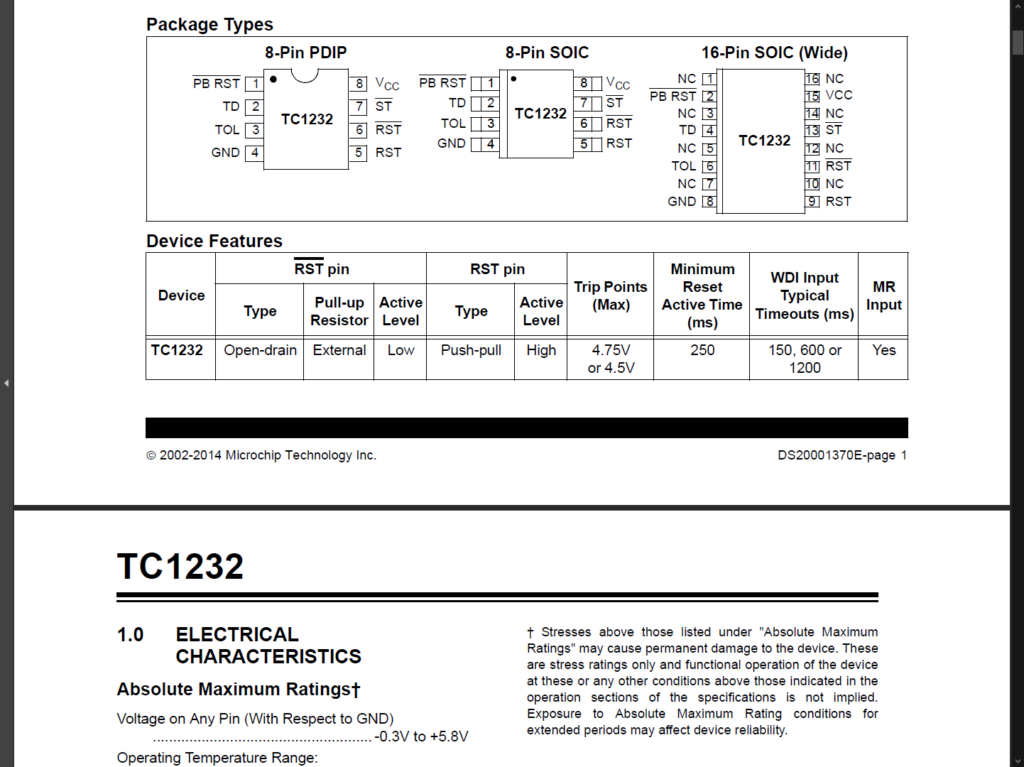
Fortunately, the chip also has an inverted / active low Reset output, so we don’t need an inverter! However, the active low Reset output is an open-drain output. Therefore, we do need an external pull-up resistor on the Reset signal.
Fortunately, for my needs, this doesn’t actually involve any additional external components, as I already have a Single In-Line resistor pack, which I used for other required pull-ups, and it has one resistor free!
That resistor is of course the 5V terminated 10K resistor that we were using with our original reset circuit, so it’s simply redeployed as our TC1232 Reset pull-up. Perfect.
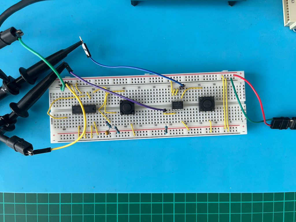
Breadboard Reset Prototype
To test and compare the Resets in operation, I decided to throw together the two Reset circuits on a breadboard, so I could observe their operation on my oscilloscope.
Schmitt Trigger Based Reset
Firstly, shown below is the Reset output of the Schmitt trigger based circuit, triggered by the rising edge of the 5V power line, as it exceeds about 4.75V, which is the lower limit of our typical 5% tolerance 5V regulated power supply.
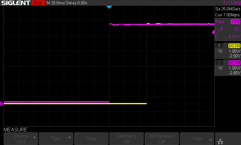
With our current choice of capacitor and resister values, combined with the threshold level of the Schmitt trigger input’s high transition (which is about 1.6V), we can see that our power-on reset state is held for about 50ms (Note: The scope is set for 20ms per division here).
Similarly, if we instead trigger the scope with the rising edge of the release of the manual reset button, with a trigger level at the threshold level of the Schmitt trigger input’s low transition (which is about 0.9V), we can also see a clean Reset state release, as shown below.
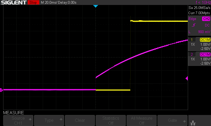
We can also see in this trace, the scope also nicely captures the capacitor voltage ramping-up, via the pull-up resistors, to the Schmitt trigger input’s high transition threshold.
TC1232 “Microprocessor Monitor” Based Reset
Now let’s look at the TC1232 Reset output.
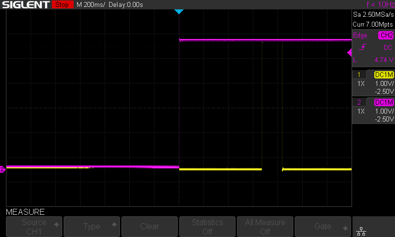
Again, we first trigger the scope with the rising edge of the 5V power line, when power exceeds about 4.75V.
With the TC1232 we can see the Reset signal being held asserted for about 660ms (Note: The scope is set for 200ms per division here).
According to the TC1232 datasheet this is typically 610ms, but can be anywhere between a minimum of 250ms and a maximum of 1000ms.
These delay times are all perfectly fine for our Retro CPU needs. In fact the 6809 CPU only requires the Reset signal to be low for a minimum of one clock cycle. But, of course, Reset can be asserted for as long as you like.
You’ll note from the scope capture, that after a further 150ms, or so, Reset asserts again for a similar period.
This is actually the expected Watchdog timer triggered Reset, as I didn’t connect a clock signal to the Strobe input pin, on our simple breadboard test.
Therefore, this also shows us that the watchdog function is working, as expected.
Okay, once again, if we instead trigger the scope with the rising edge of the manual reset button, again triggered at 0.9V, we can also see a clean reset signal release (below).
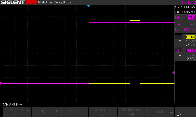
We can also see a nice clean and relatively sharp high transition of the internally pulled-up, debounced Reset button input, when we released the Reset button.
Conclusion
So, the 8-pin DIP package TC1232 based Reset looks like the simple, low cost, “Retro friendly” reset solution that I’m very happy to go with. Finally replacing the “old school” capacitor & resistors & TTL Schmitt trigger input chip based approach.
I hope you have enjoyed this little diversion on my updated Retro 8-bit CPU Reset solution.
Now, I’ll get on with finalising my updated MECB combined 6809 or 6809E CPU card design.
I look forward to seeing it. Sorry about the flood. Your doing some really great work.
Thanks for your kind words, Tom. Flood repairs have unfortunately been slow, waiting on the Insurance company, so not much has progressed on this front. Some health issues have also delayed my projects.
However, on a positive note, I have since established a temporary workspace, and I’m again working on my next post / video for my “Retro 8-bit” series, and I also have plenty of plans for future development. 🙂
Hi thanks for your reply. When I originally started filling in your AboutMe text I wrote below. Then at the end it said 180 characters or something like that!! SO here is the full text.
Well I have done a lot of 6502 programming but I always felt the 6809 was what the 6502 wanted to be. A few weeks ago someone at FabLab Imperia here in Italy was talking about building a retro Z80 based system. I can’t say I have enough experience of the Z80 to say 6809 is a better choice but I just have a feeling. So now I am hooked into designing a 6809 system and so is this other guy. In hunting for people doing 6809 projects I found digicoolthings.com and I think your project is the best I found, and your wisdom on the subject is wonderful. I have just watched all the videos carefully. What we had in common was the 100×100 board and putting the IO on another board so I really liked that. What I am designing for at the moment is splitting the 64K addressable space into four memory Banks, 0 and 1 are ram 2 and 3 are eprom. the memory chips are one 512K ram and one 512K eprom so bank 0-1 are in the first and Bank 2-3 are in the second. This provides 16 pages in each bank. However each banks page select register can select one of 256 pages giving 16Mb of addressable memory. More than I should ever want. Bank 3 memory is eclipsed from FE00 to FF00 with the page registers and anything else I decide to put there. All the vectors normally stored at the top of memory will possibly need to be duplicated on each page or I will have to also exclude FFF0 to FFFF from the page switching. Well these are my insane thoughts so far. Sorry did someone say this was meant to be a simple project to bring back old memories!? Perhaps I will run up the Archimedes again. I always liked ARM assembler as much as 6809 but 6809 is better for beginners.
Great to talk to someone on a similar journey. I’ve had experience with machine code on the 6502, Z80, and the 6809, and I must say that the 6809’s ISA is far more powerful and fun to program with than either of the others. Of course this is a subjective opinion.
You can view the 6502 as a cut down (cost reduced version) of the original Motorola 6800 architecture, whereas the 6809 is the next generation. The 6809 is, in my view, the best of the 8-bit processors. But, unfortunately, it arrived too late, when the world was already moving to 16-bit.
I had considered creating a paged memory solution, but to be honest, this thought was really driven by the relative cheapness and large capacity of memory chips these days. Back in the day we did a lot with only the 64K memory space of the 8-bit processors of the time. In fact, in the early days we were lucky if we could afford as much as 16K of RAM!
I mention this, as I believe it’s important to first carefully consider what your design goals are. For me, I want to target the retro experience we had in the early days.
In this regard there’s a lot you can do with 64K of memory. Even if I was intending to run a disk operating system, like OS/9, you can achieve most things with just 64K.
I also plan to make other CPU cards. e.g. A configurable 6502 card, which, together with an IO card and video card, could replicate like configured systems of the time.
Likewise for a Z80 CPU card.
Plenty to play with and to experience. 🙂
By the way I am not a beginner as such with a life of programming and being age 61 but in my unclear objectives on the one hand I want a 6809 based super computer and on the other I want something that a total beginner can use. Perhaps I will use a PS/2 keyboard and a 20×4 line lcd display to create the very basic programmable system. For beginners I feel it should be 32K ram 32K rom as paging memory is a bit much for them. I was also thinking that one of the small TFT displays 4″ that have their own memory and a simple interface is another way to make output that you could also write a simple space invaders or something. I saw your program about your video card but I am hesitant to use a CRT controller chip. Of course one of the reasons for using those chips was to generate PAL and not waste memory during flyback time. No memory is not an issue and PAL is not an issue so it is almost worth thinking about just clocking through memories with counters. Perhaps I haven’t thought this through properly.
It appears we are of similar ages. In regards to the video aspect, there are lots of solutions to play with. Again, one of the reasons I’m designing a modular system.
The video card I’ve designed so far is just one solution. A card could also be designed with simple logic to just directly output a block of memory to the screen, similar to early computer designs. Or, a card to interface a more modern display panel. Perhaps a graphic OLED panel with a parallel CPU interface.
This is something I’ve already been playing with, driven by the thought of creating a true retro CHIP-8 system, driving a common 128×64 OLED display (for example).
As I say, lots of options to play with.
Anyway no need for a long answer. These thoughts just came to me. I am years behind you on this project. Keep up the good work and I do hope you are thinking of selling some kits or something.
No problem. Thanks for sharing your thoughts. Always fun to talk about design possibilities.
In regards to eventually selling kits, the thought had occurred to me, if the interest is there. But, I would need to at least have enough cards designed, to support at least one initial complete system design first.
Hi again and thanks for the replies. Yes indeed. I was working for BBC Radio schools in the second half of the 1980s and I had three bytes spare. The program emulated 64 logic gates and some components with a propagation tome of 1/80th of a second. Its on this page of my CV website http://www.tomdehavas.com Imagine all that ran in under 12K, the screen used 20K and now the image on my website is 100K. I did all the artwork as well. The theatre picture and loads of fonts. No mouse, just the arrow keys and a program I wrote to draw with. On the circuits you could wire up by drawing lines any way you liked and then it compiled the circuit model. You could put a JK flip flop together out of basic gates, and or etc and see it work. All in 6502 assembler. I still have the source on 5 1/4 floppies but nothing to read them with as all disc controller chips are blown. I have a few BBC micros around and the disc drive. I should really make the effort.
Yes, those were the days. I have fond memories of developing in machine code, where in the early days you were very aware of the hardware capabilities and instruction clock cycles, as you were forced to find ways to maximise the use of the processing power available to you on the 8-bit processors of the time.
I started off hand assembling machine code on home built systems, at a time when Assemblers were out of my reach.
For some reason I always found this a more enjoyable challenge than developing in modern high level languages (part of my life’s work), where nowadays you seem to spend a lot of your development time on researching & testing layers of library functions (or classes), written by someone else.
It’s perhaps this reason, and the number of younger programmers I’ve met who don’t even understand the basics of how computer hardware works, that drives me to rediscover my enjoyment of retro 8-bit systems.
Of course, I’d encourage you to dig out those BBC micros & disk drive and get them up and running, to rediscover your earlier work. 🙂
As far as selling your products, I guess once you have RS485 or something like that it is an item that can be used.
My intention, for my first IO card, is to just terminate the UART to a TTL level header, given the common availability of USB to TTL converter modules for using a modern PC as a terminal.
PS/2 keyboard interfacing is also an option, as is just interfacing a Hex matrix keypad for that real early-retro stand-alone experience. 🙂