
Following my recent 6809 system testing video, a viewer asked if the system could run at 3Mhz, or perhaps even a little higher.
Join me as I initially test the system at 3Mhz, and then push even further beyond the manufacturer’s speed ratings.
In my last video I fully tested the system running at the official Motorola datasheet maximum clock speed of 2Mhz, the official rating of the fastest Motorola ‘B’ speed grade chips.
Noting that I do have some Hitachi HD63C09 CPU chips, all I had to do was get hold of a 12Mhz Oscillator, to allow a 3Mhz system clock speed test via the standard divide by 4 clock.
Unlike Motorola, Hitachi went to a ‘C’ speed grade with their 6309 version of the 6809, officially supporting a 3Mhz clock speed with the HD63C09.
The 63C09 chips that I have, I’d earlier put aside, as they were one of the mis-marked batch of chips I’d received from China.
Although marked as HD63C09P, they did in fact test as being external clock ‘E’ suffix chips.
In addition, as they had been incorrectly re-marked, I therefore didn’t even know if they were genuine Hitachi ‘C’ speed grade 3Mhz chips.
To add to this, the three Motorola peripheral chips on the Motorola I/O + Sound Card, are the fastest 2Mhz Motorola, ‘B’ speed grade chips.
So, when we try the system out at 3Mhz, we are doing it with an uncertain speed rated CPU chip, and with only 2Mhz speed rated I/O chips.
But, there is only one way to find out if it’ll work, and that’s to give it a test!
If it does work, we also know that our bus system is performing well.
So, without further ado, let’s get our current ‘B’ speed grade CPU swapped out for our questionable ‘C’ speed grade CPU.
First I’m going to test we are still operational at 2Mhz with the new CPU chip.
And we are looking good.
So, next up, let’s swap out the 8Mhz Oscillator for my, just received 12Mhz Oscillator, to deliver a 3Mhz system clock speed.
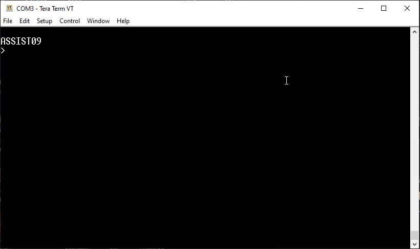
So we progress to our first 3Mhz power-on test!
And, again, we have our ASSIST09 prompt at 3Mhz, which is also indicating that in addition to our CPU Card and Backplane working at 3Mhz, our 2Mhz rated MC68B50 ACIA is also working at 3Mhz.
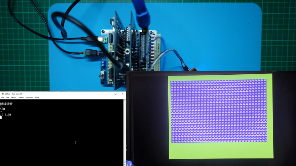
To check the system out more fully, I’ll load our Initial Test program (presented in a previous post / video), that displays a test image and then cycles through the backdrop colours on our TMS9929A Video Card.
For this test, I also took the opportunity to first test our 2Mhz MC68B40 Programmable Timer Module (PTM), is still working, by setting a breakpoint and also doing a single step.
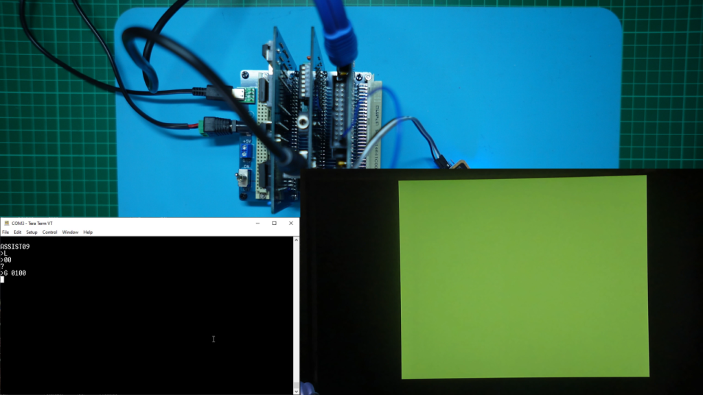
I set a breakpoint at the start address of $0100 and ran our test program.
The program stopped immediately at the $0100 breakpoint. I then did a single step, by pressing . Either of which confirm our PTM is also working at 3Mhz.
After single stepping, I entered G to continue our test program.
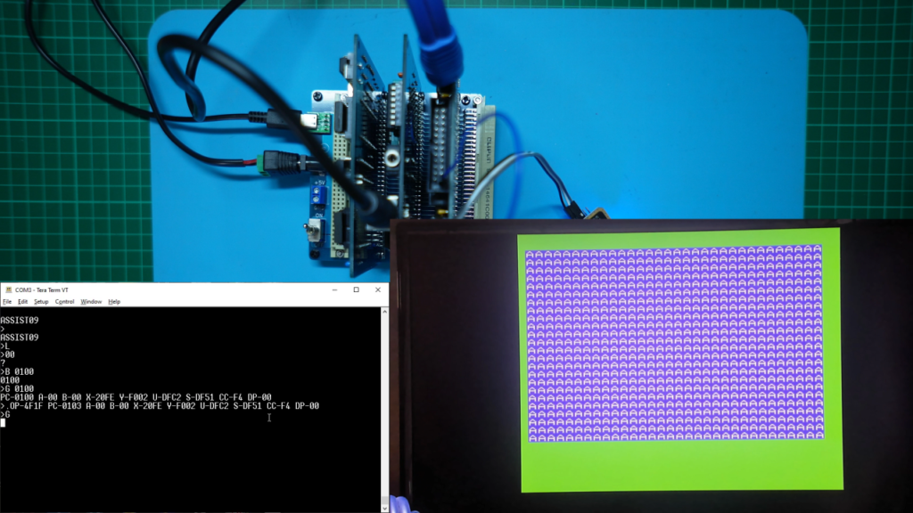
It looks great! The original 2 second software delay loop (based on a 1 Mhz clock speed), which was changing backdrop colour every second at 2Mhz, was now changing even faster when running at 3Mhz.
So far, we are looking good, as a successfully running 3Mhz 6309 system!
So, since we’re here, I do also have a 16Mhz Oscillator.
How confident do we feel about pushing our 2Mhz rated Motorola peripheral chips out to double the rated speed, with 4Mhz?
I’d say it would have to be questionable. But since I have a 16Mhz oscillator handy, let’s give it a shot.
Firstly, we should consider some obvious potential timing constraints. Specifically, we can consider our memory timing.
With a 1Mhz system clock we have a 1µs clock cycle, at 2Mhz we have a 500ns clock cycle.
Stretching to a 4Mhz clock, gives us only a 250ns clock cycle.
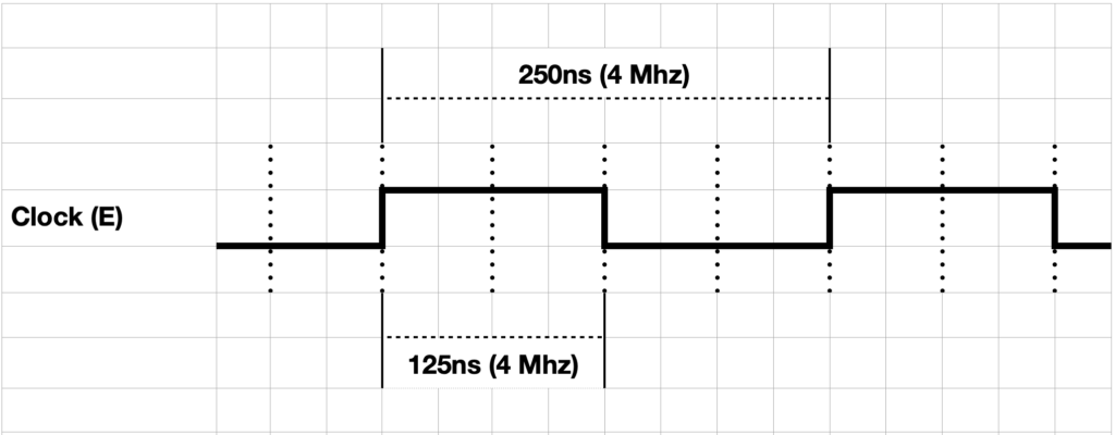
Now, some simpler 6809 system designs that I’ve seen, only utilise the ‘E’ clock in their memory decode logic. This only allows a half clock cycle for memory access (effectively limiting memory access to just within the ‘E’ clock’s high period).
This means that at a potential 4Mhz system clock, you only have 125ns of high level ‘E’ clock period per cycle. When you also allow for glue-logic propagation delays etc. you’d probably be restricted to only 100ns or faster memory access speeds.
Fortunately, the Motorola 6809 introduced a Quadrature clock (Q), with Valid Memory Addresses (VMA) being available at the rising edge of the ‘Q’ clock cycle.
To utilise this longer available memory access period, it was common to gate the ‘E’ and ‘Q’ clocks (‘E’ or ‘Q’ high), to effectively achieve a longer three quarters of a clock period for memory access.
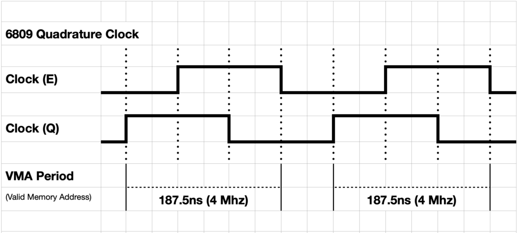
This is exactly what I’d already done, when I originally defined our 6809 CPU Card PLD glue logic.
Therefore, instead of being limited to around 100ns or faster memory at 4Mhz, the now three quarters of a 4Mhz clock cycle for memory access, gives us about 187ns to work with.
Allowing for the propagation through our glue-logic PLD (which is a max 15ns), we probably actually have around 170ns available for memory access.
Looking at our CPU Card memory we have a very fast Static RAM chip, in the order of 15ns access time, therefore RAM access is not going to be an issue.
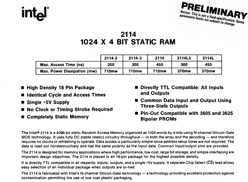
For our ROM we are currently using an AT28C256-15 chip. The -15 suffix indicating 150ns access time.
Therefore, it’s looking like we’ll probably still be okay at a 4Mhz system clock, with the ~170ns available memory access window, as far as our memory access is concerned.
It’s interesting to note that back in the day, or at least in the late 70’s or early 80’s, 450ns was the more commonly available memory Access Time, with the memory parts commonly available to hobbyists. More expensive devices could be located, offering 300ns, or 250ns access times. But memory chips were relatively expensive in those days.
It’s clear to see that memory access times, in the early days, also played a big part in determining actual achievable system speeds.
So, with potential memory access timing constraiants aside, we are back to the question of whether our 2Mhz rated Motorola peripheral chips, and our 3Mhz rated Hitachi CPU will operate at 4Mhz?
If it works, not only would that be surprising, but it’ll also be proving our MECB bus and backplane running at a system clock speed that we’d probably run a Z80 at.
Note though that a Hitachi 6309 running at 4Mhz has significantly more performance capability than a Z80 at the same clock speed. Arguably, I’d hazard a guess that a 6809 is probably around 3 times the performance of a Z80 (at the same clock speed!).
I believe the 6502 is generally argued as being twice, or even two and a half times, the performance of a Z80, at the same clock speed.
So it seems reasonable to speculate that our Hitachi 6309 running at 4Mhz is perhaps equivalent in capable performance to a Z80 running at maybe 12Mhz! (note: Pure speculation on my part only!).
Never the less, this speed is something we would have only dreamed of having, back in the early days of the late 1970’s and early 1980’s.
So, at this point we’re ready to give it a try.
I just swap out the 12Mhz oscillator with my 16Mhz oscillator, and power up!
And, almost unbelievably, we obtain our normal ASSIST09 prompt, at 4Mhz system clock speed!
So, again we now know our CPU Card, bus, and our 2Mhz rated MC68B50 ACIA are all now running at 4Mhz.
So, then we can test the rest of the system out at 4Mhz.
Firstly, with our earlier “Initial Test” program for the Video Card, with its software loop delayed cycling of the backdrop colours.
We transferred that program across, and ran it.
Okay, we observe that we are missing our test image pattern, but the backdrop color is successfully displaying and quickly changing colors.
This is actually great news!
It suggests everything is actually running okay, but that we are just having some access timing issues with the TMS9929A VDP chip and it’s connected VRAM access.
This isn’t actually at all surprising, as the TMS VDP chip does take some time to access the VRAM, so if the processor is too fast, it can be trying to write the next byte to the TMS9929A, before the TMS VDP has completed storing the previous VRAM byte etc.
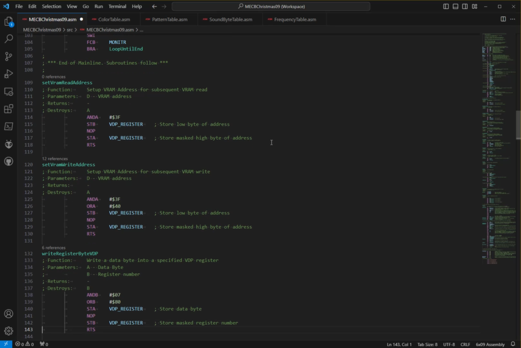
The solution to this timing issue is often as simple as adding a NOP instruction into any tight loops writing blocks into the VDP’s VRAM, or any other sequential accesses of the VDP.
A NOP instruction simply increments the Program Counter and takes 2 cycles, therefore adding a small delay.
I do recall being surprised that no access delays were actually required when I first tested the VDP, even at just 1Mhz, so the possibility of needing a small NOP delay to support a 4Mhz clock speed is not at all surprising.
So let’s try that out, by adding some NOP instructions to our six core VDP access subroutines.
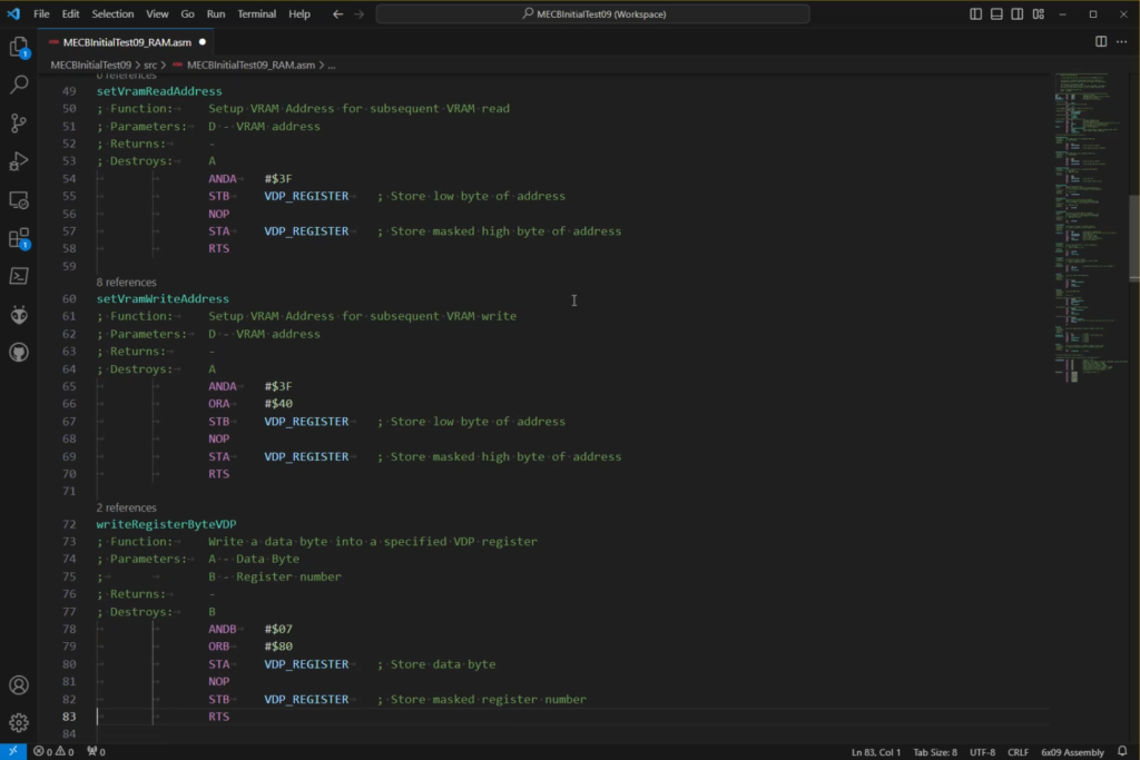
With some NOP’s added in the appropriate VDP subroutines, we re-assembled the code and transferred our program across again.
And we have Initial Test success, at a very fast 4Mhz. Twice the Motorola rated clock speed!
We also noticed how quickly the backdrop color is now changing, based on our original 1Mhz coded 2 second delay loop!
At 4x speed we are seeing a backdrop color change every half a second!
Next, the final test, to check the rest of the system, is to make the same NOP additions to our “Christmas Demo” (presented in a previous post / video), VDP subroutines. Then check that we have sound.
This will perform the final test that the both the MC68B21 PIA and the SN76489A Sound chip are also running okay at 4Mhz.
Note, the sound will still play at the right tempo, because we can recall that the sound is being updated via the 20ms Frame Interrupt (from the 50Hz PAL Video chip), making it independent of the system clock speed.
What we will probably notice is that the music notes themselves will be playing at double the intended frequency, as we are now clocking the sound chip at 4Mhz, instead of the 2Mhz that the “Christmas Demo” frequency table was originally written for.
So, with the NOP’s added, we assembled and transferred the “Christmas Demo” across to our 6809 system.
And, finally, we run the modified program to see what we get.
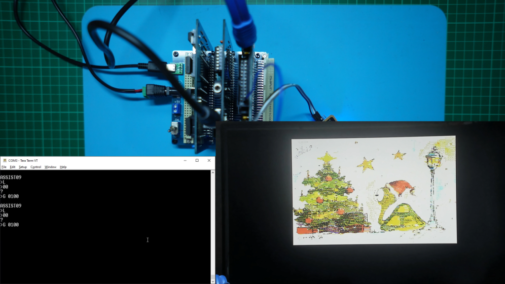
The result was really awesome!
Almost unbelievably, we have a fully working 6309 system with I/O and Video, running at 4Mhz!
I also checked that after running for a reasonable time, none of our chips are getting excessively hot.
Success!
As a result, I’ve also committed the NOP code additions (commented-out, with the appropraite 4Mhz usage comments), to the MECB github repository, for both the Initial Test and the full Christmas Demo programs.
Now, before finishing up, there’s a couple of remaining tests that I think would be interesting to do.
Firstly, I decided to swap-out the 3Mhz speed grade HD63C09, for the earlier 2Mhz HD63B09E CPU, which I was originally using.
I thought it would be interesting to see if the 2Mhz ‘B’ speed grade Hitachi 63B09 would also work at 4Mhz, just like the 2Mhz Motorola peripheral chips are successfully doing.
Also, the HD63B09E chip that I have, is a known legitimate Hitachi 2Mhz part, as it is the chip that I had used some Acetone to rub-off the false markings.
Below is the chip, as I received it. Note it is marked as a HD63B09P.
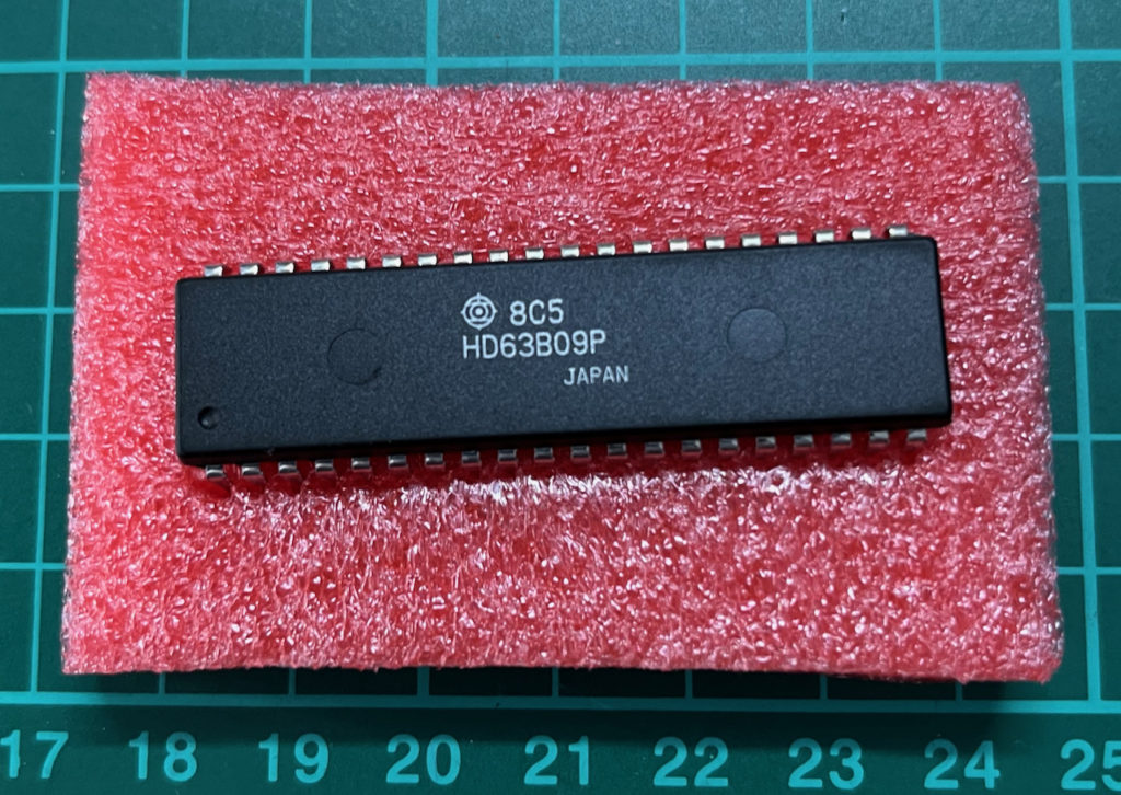
Below is the same chip after some Acetone rubbing, revealing the original chip markings, in fact a HD63B09EP (External clock).
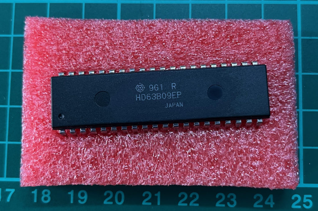
Also the date code (9G1) indicates that this chip was manufactured in the first week of July, in a year ending in 9.
Given that the HD6309 was launched in 1982, we therefore determine this particular chip was from at least 1989.
So, I swapped over the CPU chip, and once again applied power.
And, once again we got our ASSIST09 prompt. So, we’ll call that another 4Mhz test Success!
Next, I decided to finish-off by swapping back to an original Motorola MC68B09 2Mhz CPU, just to see if that will also work at 4Mhz.
This turned out to be more interesting. Perhaps less surprisingly, my original MC68B09P (Internal Clock), which had been in my parts drawer since the 1980’s, was our first failure at 4Mhz.
I’d speculate that either this was an earlier MC68B09 fabrication, that was more likely to be limited to the published 2Mhz speed rating, or perhaps it was just simply that the Internal clock divider couldn’t cope with a 16Mhz oscillator clock input?
Whatever the reason, I simply repeated the MC68B09 test with an External clock MC68B09E that I recently sourced from AliExpress. As this is no-doubt also a re-marked chip, we can’t immediately compare fabrication dates.
This time we successfully received our ASSIST09 prompt. So, we’ll call that a 4Mhz Success also.
Therefore, in addition to our earlier successful HD6309 4Mhz tests, we now have a fully 2Mhz Motorola ‘B’ speed grade MC6809 system, running successfully at twice the official rated max clock speed (ie. running at 4Mhz instead of 2Mhz!).
I think that for our success, we can thank Motorola Engineering, as well as the ATF series PLD fast propagation delay (fast glue-logic), and the more modern Retro memory chip faster access times.
In fact, our actual speed limit appears likely to be mostly constrained by the 28C256 ROM’s 150ns access speed.
As a parting note, I want to emphasise that over-clocking is not my motivation. These speed tests were simply an exercise to test the capabilities of the MECB based system to support the maximum documented speed of the Motorola 6809 and Hitachi 6309 CPU’s.
I’m aware others have pushed the speed of retro 8-bit CPU’s even higher, but as I’ve mentioned, potential over-clocking ability is not the motivation of this project. The MECB project is purely to facilitate (and re-live), experimenting with the various 8-bit devices, as we did in the early 1980’s.
So, I think we can say that our “Push our 6809 Speed” test was an outstanding success!
Oh, Yes!! 😀
Yes, you are the Scott I was refering to at the start of the video. Thanks for prompting me to make this video / post. 🙂
Awesome! I had read that some speedsters had run some 63C09’s up to 5Mhz, I can’t imagine that’d be good for them, but given a 3Mhz system would be plenty quick, it sure does open up plenty of scope for hacking and modding! I’m still struggling to come to grips with KiCAD, but I’m sure it’ll be clearer than mud soon. Curious to know more about your chip testers though, that seems like it’d be a handy tool given the batch I’ve ordered. Did you make those yourself, or are they available somewhere else?
Great episode, btw – I sure did get a lot out of it!! Thanks!
😀
Thanks. Keep going with your KiCAD learning! As I imagine you already know, it just takes practice & repetition to become proficient with new skills. 🙂
Yes, the NOP CPU testers are a really useful tool to have when ordering these recovered retro CPU parts.
If you’d like to know more about these testers, I discussed them in full detail in my video / post: “More AliExpress Re-Marked Chips Frustration (EPROMs & 6809 / 6309 CPUs)“
Hey, Wait, did I see you have more than one of each of those PCBs? What are you doing with all those other ones, you’re not running a sweatshop of multi-line stress tested CPUs, are you??
Do you mean more than one of each of the MECB PCBs?
I’ve only built-up one of each of the MECB board revisions, but I do have additional PCB’s in stock (for each of the latest revisions), in case anybody orders them through my Tindie store.
At the time of writing, I still have the 6809 CPU Card and the Motorola I/O Card to get listed on Tindie, the earlier boards are already listed.
Just a matter of me finding some time to get these two latest boards listed, in between working on the next project / video / blog. 🙂
Hmmm, okay, I was looking at the CPU test PCBs as mentioned in the previous blog about AliExpress CPUs, but since you mention it, the only items I can see are the EPROM flasher, two versions of your hex keyboards, the MECB backplane, TMS992xA VDP board and MECB prototype board – nothing else – and certainly not the CPU testers you have multiples of from what I saw, right?
Ahh, yes. Apologies, my misunderstanding. I do indeed have some spare PCB’s for the CPU testers.
I had to order five of each, and I’ve only used one of each. So, I’m quite happy to give you one of the spare PCBs for each of the MC6809 and MC6809E CPU testers, so you can also build them. Just a matter of covering my shipping cost.
As a thought, if you were to order something from my Tindie Store, I could then include a couple of CPU Tester PCBs in that delivery, as the order would cover the shipping cost.
If you’re interested in building the complete 6809 MECB system that I’ve built so far, probably best to hold-off until I also get the 6809 CPU Card and Motorola I/O card listed, so that you can get the full set together to save with combined shipping.
I’ll hopefully get these listed soon. It’s just has been quite time consuming putting the photos, BOM, costing, and the description together, to create the product listings. I’ll try to focus on this over the next week or so.
p.s. – I’ve arranged with my wife & family to get me a bunch of these cards for Christmas – so the more you have listed, the more I’ll be getting, and I’d even suggest listing those surplus CPU testers too if you don’t have other plans for them – no pressure or nuthn…
😐