
Having finally assembled an initial 6809 based system, following the completion of my recent Motorola I/O + Sound card, we should now give the system a bit more thorough testing.
Join me, as I first test the system running at twice speed, and then walk-through several test programs to verify everything, including Interrupts and Sound, are all working, and at the faster system speed.
My earlier presentations of the 6809 CPU card included testing it with the TMS9929 Video Display card.
I also initially tested the Motorola I/O card with a simple “Hello World” program.
Both of these tests were run at just the base 1Mhz clock speed of the original MC6809 processor.
My Motorola I/O card introduction did include successfully testing both the ACIA and PTM chips, as they’re both utilised by the ASSIST09 monitor, for serial terminal communication and for enabling breakpoints and single stepping.
These tests were also done at the initial 1Mhz system clock speed.
As you’ll probably know, the Motorola MC6809 was available in three clock speeds.
First, was the initial 1Mhz speed, then the 1.5Mhz “A” version (the MC68A09). Finally, the 2Mhz “B” version (MC68B09).
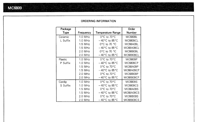
Matching ‘A’ and ‘B’ peripheral chips, for 1.5Mhz and 2Mhz, also supported these faster speeds.
So, the first thing I want to verify is that the cards developed so far, and the bus system itself, operates at the full 2Mhz speed of the ‘B’ parts.
In addition, I still need to test both the PIA and the SN76489 Sound chip functionality of the Motorola I/O + Sound card.
So, first up, I’ll ensure we have fully populated our boards with the faster 2Mhz “B” speed grade CPU and Peripheral chips.
And, it appears we already have. The I/O card already contains a MC68B21 PIA, a MC68B50 ACIA, and a MC68B40 PTM.
Also, the CPU card is currently populated with a Hitachi HD63B09 CPU chip, also rated for 2Mhz.
Now, remembering that a 6809 system uses a divide by four clock, we currently have a 4Mhz crystal oscillator installed on the CPU card, to provide the 1Mhz system clock.
So, with all the correct “B” grade chips in place, we simply need to swap the 4Mhz crystal oscillator, for an 8MHz oscillator, to provide the double-speed 2Mhz system clock.
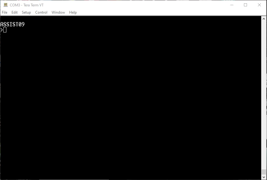
So after swapping over the crystal oscillator, we power-up and see if we’re still in business.
And, we’re looking good, with an ASSIST09 prompt.
Next up, we need to check that our video card still operates with the 2Mhz system clock.
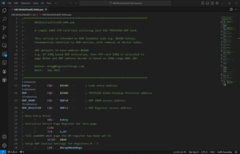
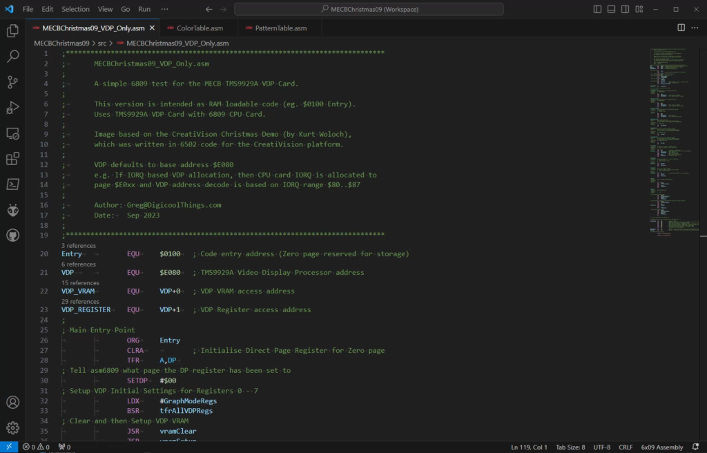
For this test, I’ve taken our original ROM based VDP Card test code, and modified it for running in RAM instead.
All that was required was to change the Origin address for Assembly from #$F000 to instead be in RAM. I’ve used address $0100.
i.e. The second page of memory located in the RAM memory space.
In addition, I’ve removed the Vector Table that was being assembled into ROM at #$FFF0 – #$FFFF.
Finally, I’ve removed some of the initialisation code, which is now already taken care of by the ASSIST09 monitor.
So, I then transfer the assembled .S19 file across to our CPU Card, with the ASSIST09 L command. And run the code with G 0100
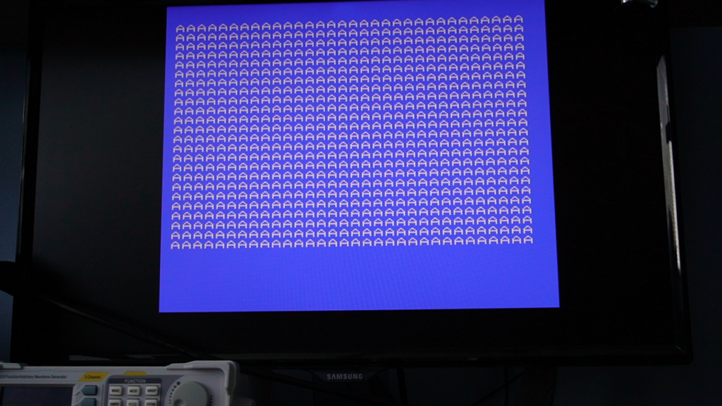
And, we have our existing Video test running as expected, with the backdrop colours being updated twice per second, instead of every second as before.
This is expected, as we had used a simple software loop for the 1 second delay, and we’re now running at twice the clock speed.
So, everything is look great at 2Mhz.
That just leaves the testing of our PIA and SN76489 Sound chips on our new Motorola I/O + Sound card.
For this, I located a simple “Christmas Demo” program that was originally written by Kurt Woloch, for the CreatiVision game console.
The CreatiVision was actually 6502 based, but it used both a TMS9929 VDP and a PIA connected SN76489 Sound generator. It also used a 2Mhz system clock for it’s 6502 and the SN76489.
On our 6809 system, running at 2Mhz, we’re also clocking our SN76489 at 2Mhz.
For these reasons the CreatiVision seemed like an ideal candidate for obtaining some existing demo code to base a test on. Although, being a 6502 based system, I’d still need to re-write everything for the 6809.
As we’re specifically wanting to test our PIA connected SN76489 Sound generator, and we have a TMS9929 based video card, this “Christmas Demo” program certainly seems like a good place to start, without having to entirely re-invent the wheel.
Instead, I can utilise some of the 6502 demo’s data resources, and then dive into re-writing the program logic for our 6809 CPU.
Noting also, that the 6502 is a little Endian processor, whereas our 6809 is big endian. Something to keep in mind when porting across data resources.
First, I ported across the graphic resources. And then wrote some appropriate 6809 code, re-using my existing VDP routines, which I’d already written for our existing test code.
The goal of first getting the Christmas graphics portion of the CreatiVision demo working.
Fortunately, the published CreatiVision Demo also had a screenshot, so we know what to expect, which will help determine if the graphic image is being presented correctly.
Appropriately for a “Christmas Demo“, it’s a Christmas themed scene.

Having created the 6809 code, we run it to see what we get…
We get just what we were expecting, so that was successful.
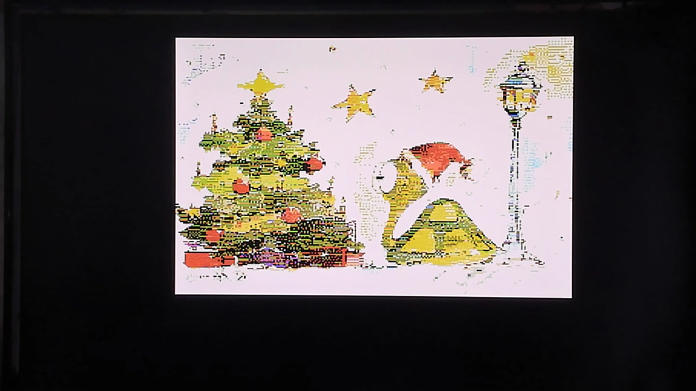
Once again, this is also confirming we have no issues with our code talking to the TMS9929 VDP at a 2Mhz system clock.
Next, after analysing the “Christmas Demo” code, I noted that the sound output is being generated by an Interrupt routine, triggered by the TMS9929’s frame interrupt.
Our TMS9929 VDP’s interrupt output is indeed connected to our CPU’s IRQ input, so we’re all set there.
So, this will also provide a good opportunity to verify that the MECB Interrupt signal and the CPU Card’s IRQ Interrupt input are functioning correctly.
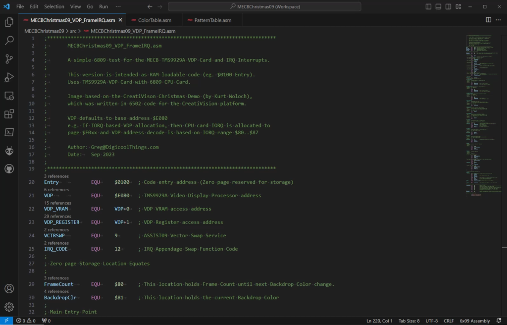
To initially test the Interrupt operation, I’ve decided to first implement a VDP frame interrupt service routine, to drive our previously written test process that was simply cycling through the VDP backdrop colours.
Therefore, instead of using our existing software delay loop, I’ll instead make use of a video frame counter and an Interrupt Service Routine, to trigger changing the backdrop colour every 50 video frames.
On our PAL system, 50 frames equates to 1 second, with an interrupt every 20ms.
This will test our Video Card Interrupts and the CPU Interrupts, are all working correctly by first using a previously proven backdrop colour change process, laying the groundwork for subsequently porting across an Interrupt driven Sound demo.
So, our second test program provides an Interrupt driven video backdrop colour cycle.
For debugging this, I also hooked-up my scope to the MECB INT line, so I could observe the Interrupt signal being driven low, and being released high again, once every 20ms.
Running the code, we are once again looking good.
We now have proved we have successful Video card and CPU card Interrupt handling.
Now, all that remains is the PIA and Sound chip test.
So next, I’ve re-written the sound functionality of the Christmas Demo for our 6809.
First I extracted two additional data resource as Include files.
One contains the music note table containing all the tune notes for all three sound channels of the SN76489. The second table contains frequency data for each of the different musical notes.
With the additional code written we’re ready for our final test!
So I transfer our final interrupt driven test program, run it with G 0100.
And the result is awesome. We have successfully ported the CreatiVision Christmas Demo to now have it running on our 6809 system, and the retro sound is awesome.
I’ll note that debugging my code was made supper easy with the Breakpoint and Single Stepping facilities of the ASSIST09 monitor.
I’ll upload all of the demos to the public MECB Github repository, in case you want to take a closer look, or even run these tests on your own MECB system.
Although some of the routines are duplicated between the demos, I decided not to extract the common routines to a separate common routines include file, just to keep the simplicity of all the code being in one source file for each demo.
To finalise, be sure to watch the linked Video if you’d actually like to hear the full run-through of the Christmas Demo music, delivered directly from our 6809 system’s retro SN76489 Sound Generator.