
In the early computing days of the late 1970’s, back when we were building our own 8-bit microprocessor systems, it may be hard to imagine now, but we didn’t actually have computers back then (of course!).
So, when we wanted to talk to our microprocessor creations, our option was either to get our hands on a Serial Terminal, or, to build our own Input / Output solution.
As owning a Serial Terminal was well beyond the budget of a young hobbyist in the late 1970’s, our homebrew solution would generally involve a Hex Keypad, hooked up to an 8-bit I/O port, and some form of output, typically via 7-segment LED displays.
Later, we would build our own parallel ASCII QWERTY keyboards, using surplus keyboards, which we would wire-up in a matrix to connect with a popular ASCII keyboard encoder chip of the day.
Like the National Semiconductor MM5740. A 40 pin DIL Keyboard Encoder chip.
We’d also make some form of homebrew “TV Typewriter”, to act as our hobbyist video terminal.
Nowadays, for talking to our retro 8-bit microprocessor boards, we can just fire-up a free Terminal application (like TeraTerm), on any spare computer with a USB serial interface, and we have ourselves a Serial Terminal.
But sometimes, when we want to feel a bit more nostalgic, it would be nice to be able to fire-up a completely standalone dedicated Serial Terminal system, for talking to our retro 8-bit microprocessor creations.
This is where VersaTerm comes in.
Join me, as I walk through my assembly of a VersaTerm serial terminal, and get reminded of good practice, via a good end of year project assembly lesson!
VersaTerm is a relatively recent creation by David Hansel.
You can find VersaTerm at David’s GitHub page.
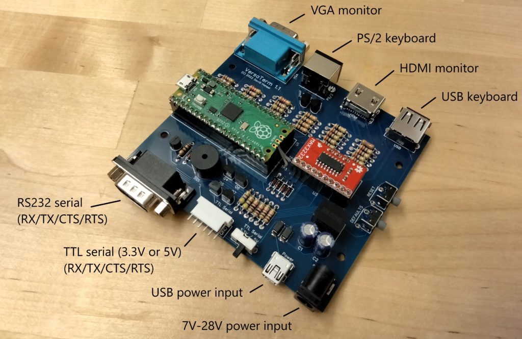
VersaTerm is a versatile D.I.Y. VT100 compatible Serial Terminal.
You can team-up your VersaTerm with either a PS/2 or USB keyboard, and either a VGA or HDMI monitor, and you then have the modern take on a versatile standalone Serial Terminal.
Perfect for your standalone, early retro computing needs.
As well as providing the gerbers (for ordering your own PCB’s), David’s github repository also provides files for 3D printing your own case, to nicely complete the build.
On printing the case, I realised that the bolt and nut holes were designed for imperial bolts and nuts. In the metric world, my closest match and my usual case screw of choice, is the metric M3 bolt.
Unfortunately, M3 bolts did not fit the imperial bolt holes. In addition, the hexagonal nut recesses were too big to allow locking an M3 nut.
So, I set about modifying the design to suit M3 bolts and nuts.
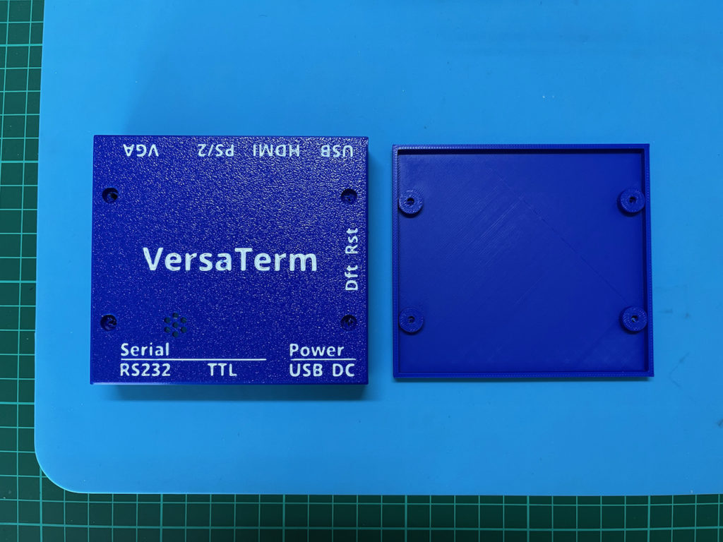
While doing this, I decided the case would benefit from some text legends to label the ports, and also provide a nice VersaTerm label.
As I had my Bambu Lab X1C with AMS for multi-color printing, I made the legends in a different color.
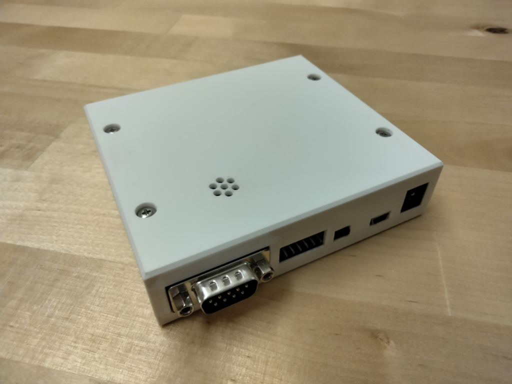
Here is the result:
I’ve uploaded this modified case design to MakerWorld.com here, and I also shared it with David.
David has since added this “metric” case option to his github repository.
So, with my case organised, and the gerbers submitted to JLCPCB for manufacture, the next was sourcing the parts.
The VersaTerm is built around a Raspberry Pi Pico board.
I happened to have a spare Pico board lying around, unused, so this added to the VersaTerm design being a good fit for me.
Of course I was already sold by the fact that the VersaTerm supports USB keyboards, as well as PS/2. Given that newer keyboards that also provide for PS/2 connection mode, seem to be getting harder to find.
David has also helpfully provided a Bill Of Materials csv file, as well as a link to add the BOM to a Digikey shopping cart.
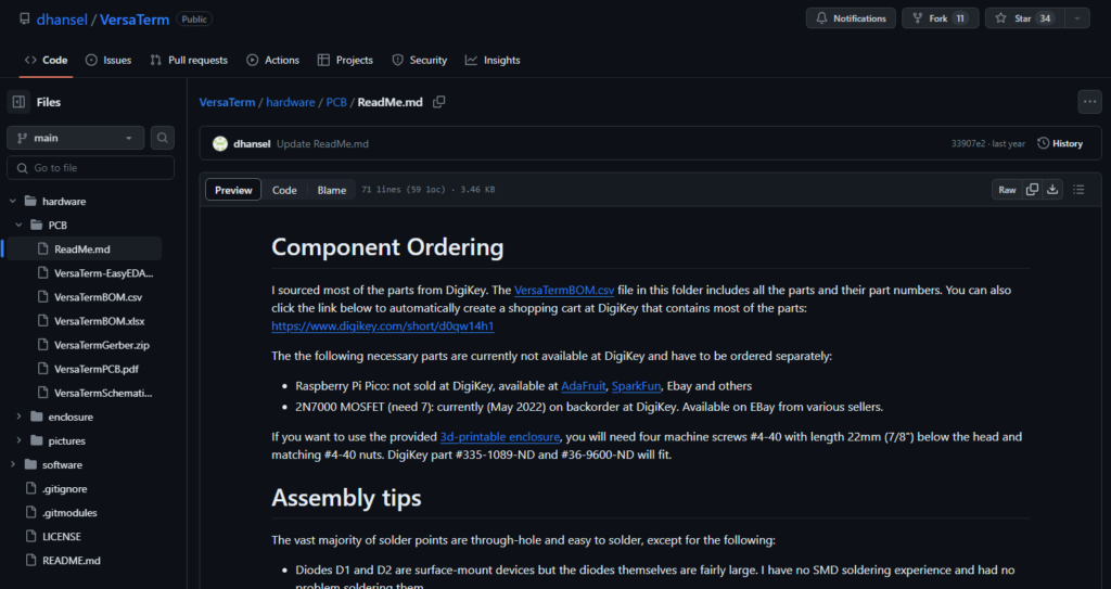
Although it has been a while since I’ve ordered from Digikey, this link made it super easy for me to just open a full shopping cart, and simply delete the lines for the parts that I knew I already had handy, and then complete the order.
So, here we are a couple of weeks later.
I’ve now received the parts ordered from Digikey, and I also have the PCB’s that I ordered from JLCPCB.
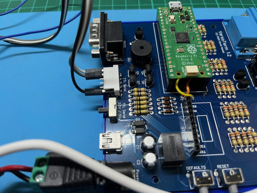
So, I’m now all ready to start assembly!
I start with the lowest profile components, which are the diodes and resisters.
Then proceed to install the remainder of the components, connectors, and switches etc, from lowest profile to highest.
Once the components on the main PCB were complete, I soldered a 10-pin header onto the MAX232 serial module, and also connected the TP2 and TP3 fly-leads from the Pico H module.
With everything assembled it was time for testing.
Being overly optimistic, I then fully assembled the VersaTerm into its 3D printed case to fully complete the assembly (before testing). Obviously tempting Murphy!
I the connected everything up, including my VGA monitor, USB keyboard, and the TTL serial connection for the ASSIST09 based MECB 6809 system.
Time to power-up… Nothing!
On first try, VersaTerm was non-responsive, not displaying any received serial data. Simply a blank screen, with a block cursor at the top.
I tried a few things first, like reverting my 6809 system to the VersaTerm default 9600 baud, removing the MAX232 module (in case it was interfering with the TTL serial), but Nothing!
So, it was time to break-out the Oscilloscope for a closer look.
This of course, required me to first dismantle VersaTerm from its case (yes, I was too optimistic before!).
First, I checked the serial signal being received from our MECB system.
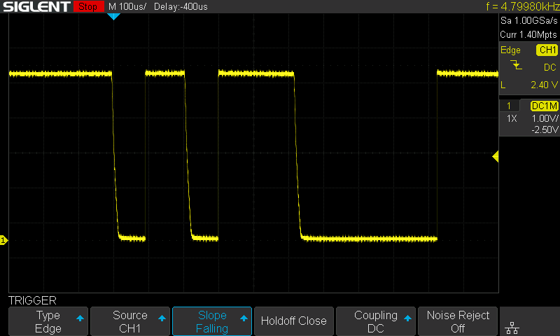
Looking good. A nice TTL level serial signal in response to pressing the Return key.
So, after consulting the circuit diagram, the next test was the signal on R29. This represents the serial 3.3V level serial data input to the Pico module.
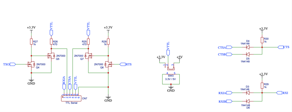
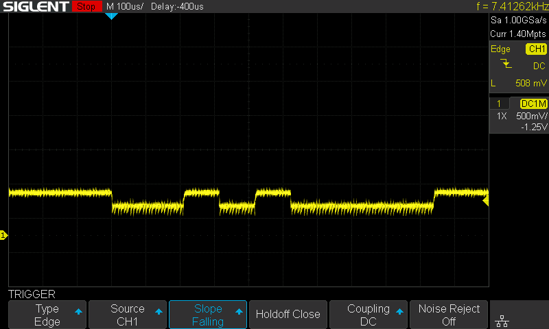
This wasn’t looking good! We were getting a significantly reduced signal of only around 200mv amplitude, around the 0.7v level.
This was enough of a clue, as I immediately then noticed that R29 was in fact a 100K resistor (Brown-Black-Yellow), instead of the correct 1K (Brown-Black-Red).
Seemingly obvious. I have no idea how I missed this, as I usually always check my components when assembling a project!
As I usually use components from my own parts drawers, I can only imagine I was too trusting of the labelled parts bag I had received from DigiKey. But, it is my fault for not checking!
So, after some re-work, removing the seven 100K resistors, and replacing them with the correct 1K values (from my parts drawer), we were finally up and running.
This time, on power-up, I received a VersaTerm intro box on the screen, which cleared when the first characters were received, and correctly displayed, from ASSIST09.
I then also configured again for 38400 baud, and everything was working as expected.
Finally, I re-assembled the VersaTerm back into its case, to complete the project.
To finish up, I still can’t get over not noticing that I’d received 100K resistors instead of the ordered 1K.
I’ve always checked my components before using them. That’s why I have a component tester that lives on my workbench!
But, 2023 has been a long year, and this video has literally taken me weeks to complete, in between constant end-of-year interruptions.
Although, I supposed on a positive note, we can call this another great reminder of what you should always do!
Check your components and values!
Also, I’ll note that videoing the full project assembly was very time consuming.
I know some people find watching electronic assembly incredibly boring, while others find it quite relaxing.
Perhaps let me know in the YouTube video comments whether this is something I should do again, or, whether you’d prefer me skipping the detailed assembly?