
I’m currently working on the design of my first I/O Card for the Minimalist Europe Card Bus.
As mentioned in my previous post / video, my intention is to first make a purely Motorola based I/O card, to stay true to my first CPU Card, which is Motorola 6809 based.
Staying true to using the Motorola peripheral chips of the early 80’s, means we will also need a Baud Rate Generator circuit for the MC6850 Asynchronous Communication Interface Adapter chip (ACIA).
Join me as I describe the original 80’s Baud Rate Generator design, and then present and test my updated “3 component” Baud Rate Generator for my new MECB I/O Card design.
Unlike the more commonly used MOS Technology 6551 ACIA, the original Motorola 6850 doesn’t include an on-chip baud rate generator, so it’s necessary to generate the transmit and receive clocks externally.
With the Motorola 6850 you need to supply a clock that is either 16 or 64 times the desired baud rate.
A divide by 1 option is also available, but this requires the clock transitions to be synchronised with the data stream. Whereas, for the divide by 16 or divide by 64 options, the MC6850 does feature internal clock synchronisation to the data stream.
Therefore, the divide by 1 option is really only useful in an application where you are receiving a data stream that includes a synchronised clock signal.
Taking a look at my original early 80’s wire-wrap 6809 Eurocard, the Baud Rate Generator was created using a 2.4576Mhz crystal, a couple of resistors, a TTL 7404 Hex Inverter, a CMOS 4040 12 stage Binary Counter, and an 8-way Dual In-Line switch.
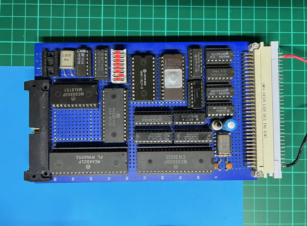

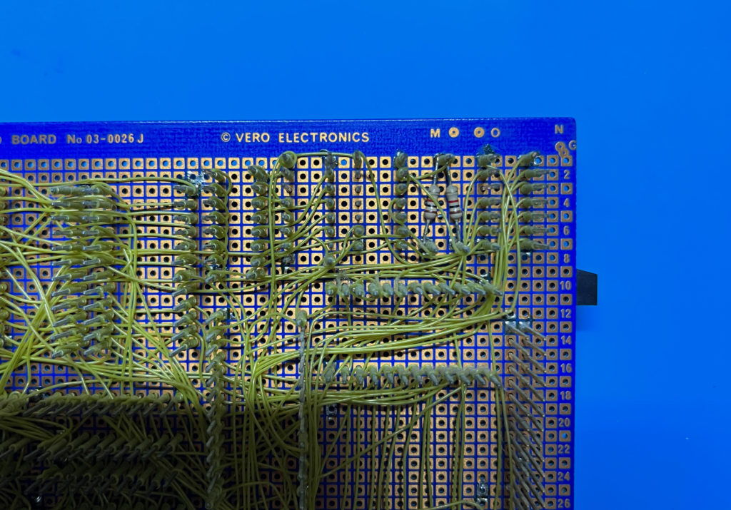
Here is the circuit, which, as I’ve no longer got my circuit diagram, I’ve re-created by reverse engineering my original wire-wrap board.

These commonly available components, together with different crystal frequencies, were typical for a baud rate generation circuit in the early 80’s.
For my updated I/O card, I want a simplified and cleaner design, and perhaps also just making do with 4 baud rate options, instead of the 8 that I originally provided.
So, here is an updated circuit that I’ve come up with.
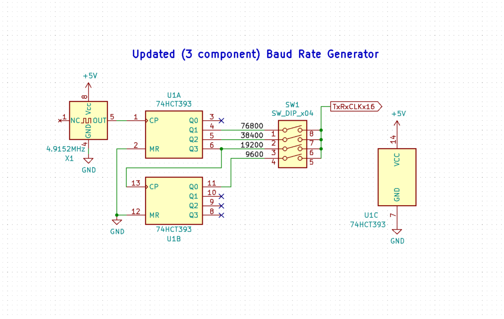
In place of the 2.4576Mhz crystal, resistors, and the TTL 7404 Hex Inverter, I’m instead using a self-contained TTL 4.9152MHz Crystal Oscillator.
This frequency is twice the original crystal frequency, but 4.9152MHz Oscillators are more commonly available.
Then, in place of the original 16-pin CMOS 4040 Ripple Counter, I’m instead using a 74HCT393 Dual 4-bit Ripple Counter, which also comes in a smaller 14-pin package.
Finally, I use a smaller 4-way Dual In-Line Switch for selecting 3 of the common faster baud rates of the period, being 9600, 19200, and 38400 baud.
I was tossing up between making the 4th selectable speed the more expected 4800 baud, or, to select a higher speed instead.
Given that it’s unlikely I’ll actually use anything less than 9600 baud, I decided to make the fourth baud rate the less common 76800 baud, being twice the 38400 rate.
Assuming we use the divide by 16 MC6850 Clock option, that means we will need:
- 153.6kHz for 9600 baud
- 307.2kHz for 19200 baud
- 614.4kHz for 38400 baud
- 1.2288MHz for 76800 baud.
These frequencies equate to the 4.9152MHz Oscillator being divided by 32, 16, 8, and 4.
By wiring the 74HCT393 Dual 4-way Ripple Counter into a single 8-way Counter, that gives us 8 possible outputs to select from, ranging from a divide by 2, through to a divide by 256.
So this updated circuit gives us a more compact, 3 component only, retro friendly Baud Rate generator for the MC6850 ACIA.
But, before I dive into manufacturing a PCB containing this circuit, I thought I’d do the right thing, and first verify the circuit on a breadboard.
All we need is the Crystal Oscillator, and a 74HCT393 chip, and then I can check the outputs we want to use, with our oscilloscope.
So, here’s my simple circuit on a breadboard.

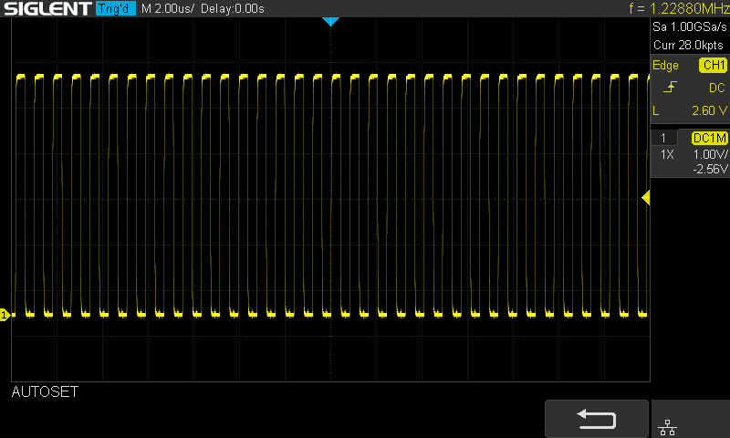
I then hooked up the scope to see if we’re getting what we want, for our required Baud Rate frequencies.
First, on pin 4 we are getting the expected divide by 4, which is 1.2288MHz for 76800 baud.
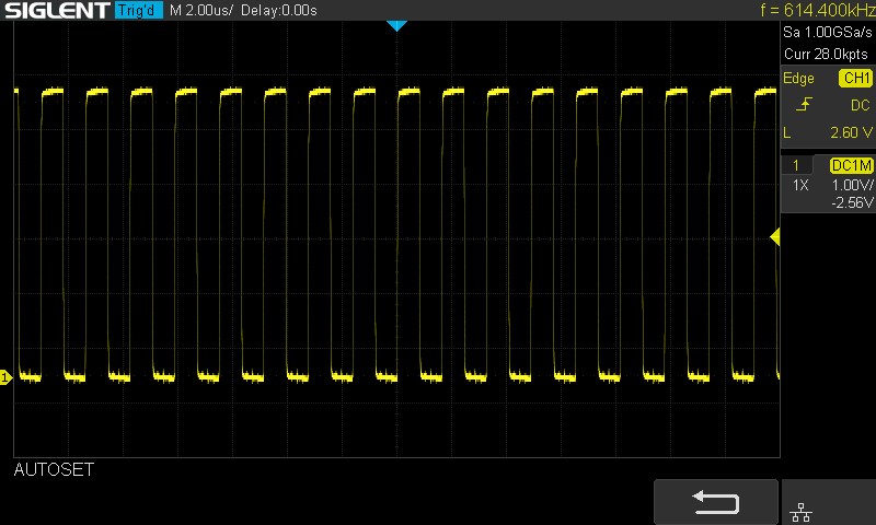
Then, on pin 5 we are getting the expected divide by 8, which is 614.4kHz for 38400 baud.
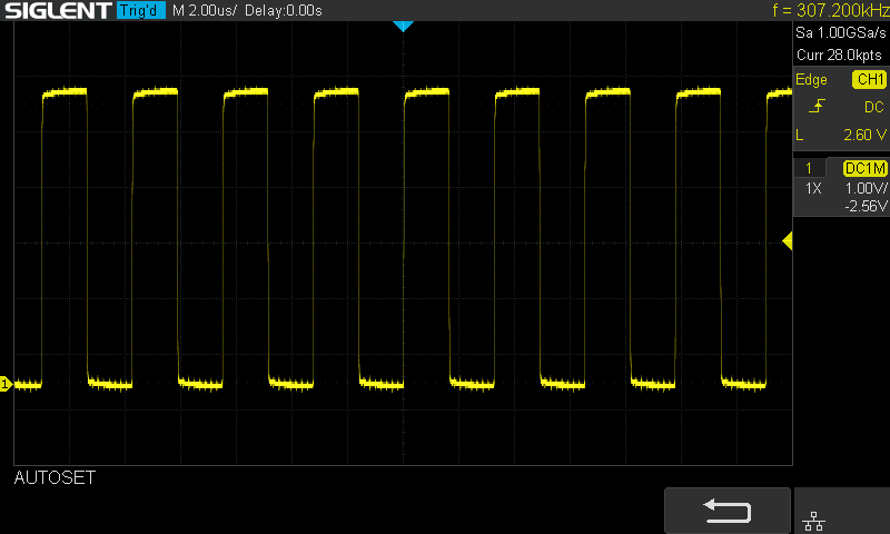
On pin 6 we are getting the expected divide by 16, which is 307.2kHz for 19200 baud.
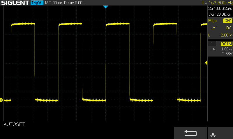
And finally, on pin 11 we are getting the expected divide by 32, which is 153.6kHz for 9600 baud.
So, all is looking good!
Therefore, next I’ll move on to finalising my MECB I/O Card schematic and the PCB layout.
Once this is done, and I’ve received my first prototype PCBs, I’ll present and test my first I/O card for the Minimalist Europe Card Bus.
Until then…