
I’ve added a modern PICO9918 based VDP Display Card, to join my existing TMS9918 / TMS992x and my existing V9938 / V9958 VDP Display Cards.
This new PICO9918 based MECB VDP Display Card delivers the MECB solution for ensuring that we have a VDP compatible Display Card for the future.
Join me, as I walk through the background and the evolution of this robust VDP display solution. I then assemble a HDMI connected PICO9918 VDP Display Card, and demonstrate its use with existing retro code, and with a couple of assembly language test programs.
Introduction
Last year, I designed a new VDP Display Card, to join my existing TMS9918 VDP family Display Card, and my existing V9938 VDP family Display Card.
I still enjoy using and programming my existing VDP Display Cards, but I also realise that at some point in the future it will become more and more difficult (and more expensive), to find, the reclaimed, out-of-production, original VDP chips!
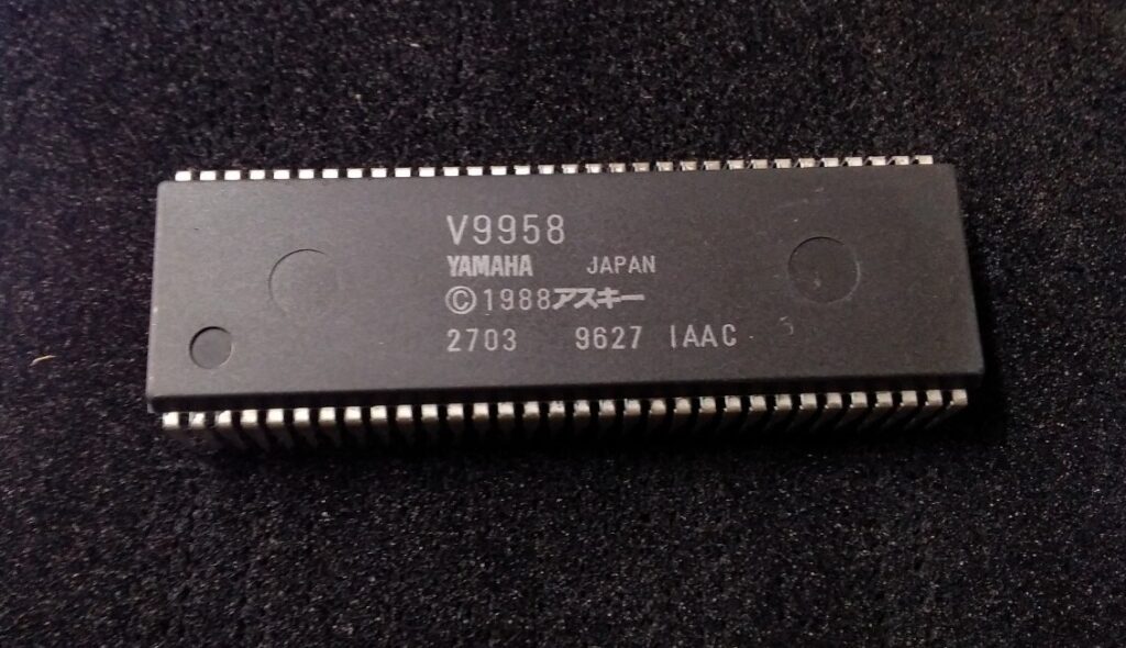
We are already seeing this happening with the V9958.
To address this, we are lucky to have dedicated retro enthusiasts, who are busy working on modern solutions for replacing these original VDP chips.
This, thankfully, means that we will have solutions for repairing & resurrecting old retro systems, well into the future.
And, of special interest to those of us who are retro experimenters, we will continue to have VDP chips, with all of their original functionality preserved, to continue to experiment with.
PICO9918 VDP Module
In this case, I’m referring to the now proven PICO9918 VDP module.
The PICO9918 has been developed by Troy Schrapel over the last few years, and continues to evolve.
It provides a 40-pin DIP compliant direct plug-in replacement for the TMS9918 family, but also implements advanced functionality, including more modern F18A capabilities.
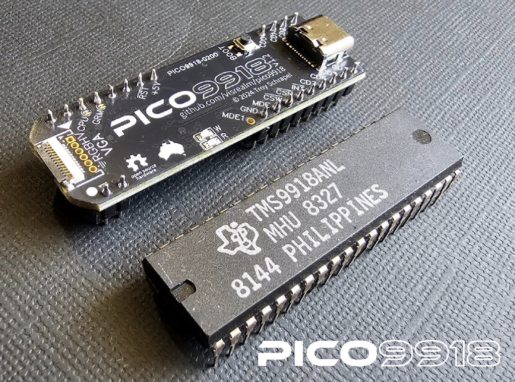
In replacing a TMS9918 chip itself, the PICO9918 also removes the use of the older, and harder to find, memory chips.
As well, it also does away with the existing video output circuitry, with all of this now handled onboard the module.
In fact, when I first designed my new MECB PICO9918 based VDP Card, last year, it basically supported a direct VGA output connector.
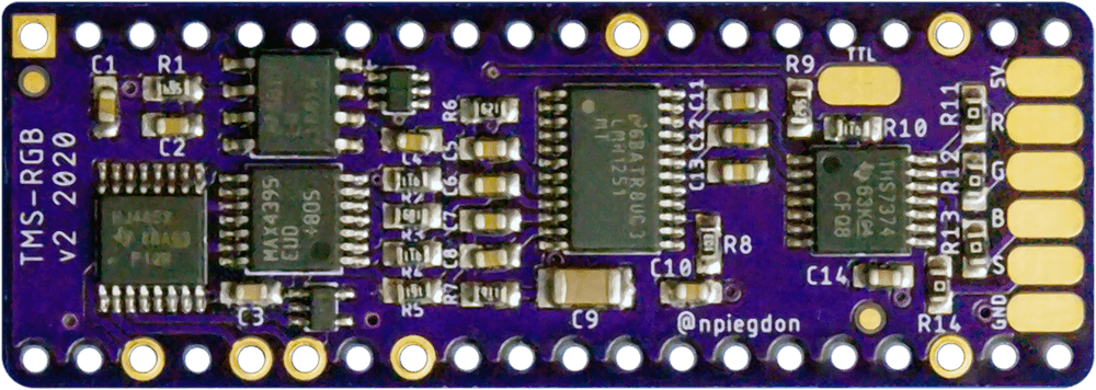
This alone was a big step forward, as it meant that I no longer needed a TMS-RGB module (to drive a clean RGBS output from a TMS9928 or TMS9929), and I also didn’t need a GBS8200 based RGBS to VGA convertor, for connecting the RGBS output to my VGA monitor.
The result of using the PICO9918, was the cleanest and sharpest VDP display that I’ve ever been able to achieve.
It really was pretty awesome.
PICO9918 Continued Evolution
Rolling forward a year, to 2026, Troy has been busy moving ahead, making his PICO9918 even better than it was last year.
Firstly, he has migrated to the newer RP2350 Pico 2, from the original RP2040 Pico. This opens up more memory and more performance for future development.
The newer Pico 2 based version is known as the PICO9918 Pro.
In addition, Troy has added a direct HDMI digital display output “dongle”, as well as a RGBS output dongle (but, more on the RGBS output dongle later).
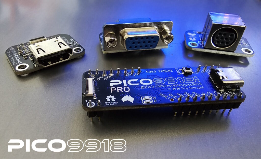
So, we now have the choice of native VGA, HDMI, or RGBS output.
Even more impressive, is that Troy has maintained backward compatibility with both the 40-pin DIP module pin-out, and with the module’s 12-pin video output connections.
So, you can still use the original VGA connectors, with the latest PICO9918 Pro module.
Finally, in addition, the earlier version 0.4.4 firmware (which I had been using since last year), has matured to version 1.2.0 (at the time of writing this blog).
MECB PICO9918 VDP Display Card
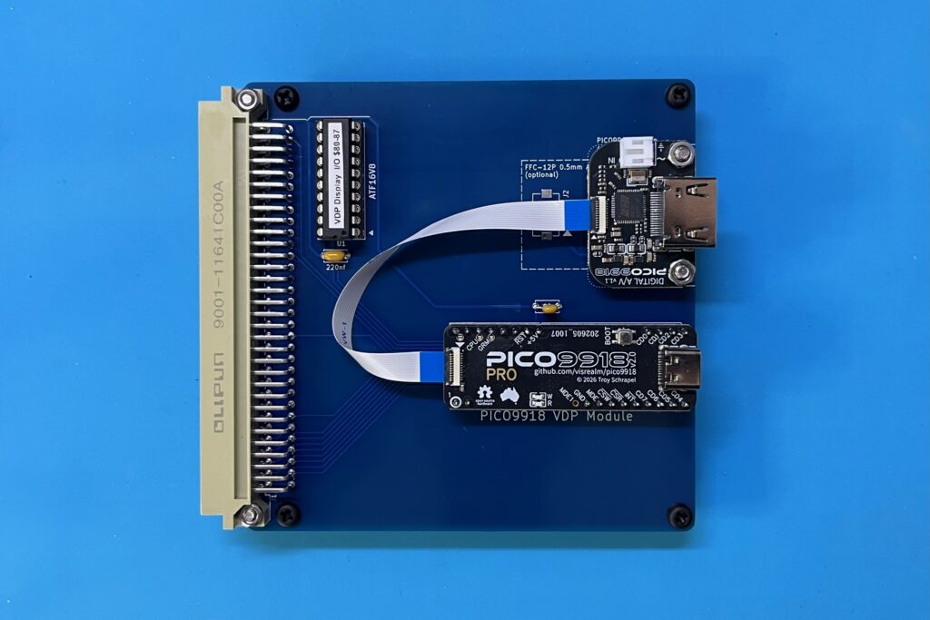
So, with the outstanding image quality, and the all-encompassing video output options, and work completed in migrating to the newer Pico 2 (with the new PICO9918 Pro), I’m now happy to officially release my PICO9918 based MECB VDP Display Card, as the MECB solution for ensuring we have a VDP compatible Display Card for the future.
Of course, I’ll also admit that I am old-school, and I do generally prefer to use original silicon, so I’ll certainly be continuing to offer my original VDP Display Cards, for as long as I can (also, this is for the reason that I’ll cover shortly).
But, I’ve got to say, that the native VGA output, along with the convenience of a HDMI output option, just blows me away with its incredibly sharp and clean display.
It provides the sort of display quality that goes beyond the TMS-RGB module output (which I use on my TMS9918 family VDP Display Card). It simply has a display quality that we couldn’t even dream of, back in the early days.
MECB PICO9918 VDP Display Card Schematic
Lets take a closer look at my MECB based PICO9918 VDP Display Card.
Below is the schematic.
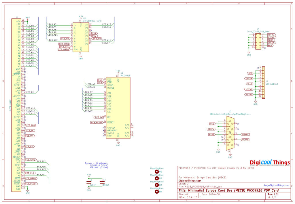
It’s pretty straight forward.
Featuring the PICO9918 module itself.
With, our standard 16V8 PLD based glue logic, which enables the flexibility of arranging your memory map how you want it, for whatever CPU card we want to use, and perhaps whatever retro system you want to re-create.
Finally, we have our on-board VGA connection components.
Just a couple of things to note.
Firstly, I created my own PICO9918 KiCAD symbol and footprint. This was pretty straight forward.
Secondly, although the PICO9918 currently comes with its Mode 1 MDE1 PCB pad unconnected (as can be seen in the earlier photo of the PICO9918 Pro). With no header pin, so, it’s not connected. I’ve connected the associated pad on the PCB to address line 1 A1, so that it’s all ready to be connected in the future.
I don’t know for sure, but I suspect this second mode pin MDE1 is intended for future full V9938 support, and since Mode 0 MDE is logically connected to the low order A0 address line, it’s logical that Mode 1 would eventually connect to A1
MECB PICO9918 VDP Display Card PCB
Let’s now take a look at the PCB 3D render.
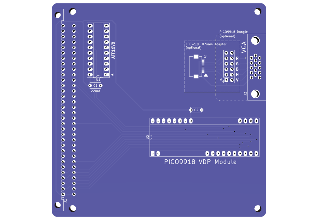
First, you’ll note that it’s a pretty plain MECB Card.
Basically, because all of the memory and video output is contained within the DIP40 PICO9918 module.
Therefore, the MECB PICO9918 VDP Display Card is effectively a carrier for the PICO9918 module itself, combining it with our usual MECB standard PLD glue logic, to interface with our MECB bus, and (of course), your selected video output connection.
MECB PICO9918 VDP Display Card Kitset
As usual, what I will be offering via my online store is either just the PCB only, or, the PCB combined with optional packs to make up a full Kitset, with the sole exception of the PICO9918 module itself and any associated HDMI or RGBS output “dongles” from Troy (visrealm), which you might prefer, instead of the onboard VGA output connector.
The good thing is that Troy sells the PICO9918 via the same online store platforms that I currently use. Either Tindie, or Lectronz.
So, you can basically add my MECB PICO9918 VDP Display Card to your shopping cart, with the optional on-board VGA pack (if desired), and then also add to your cart, Troy’s PICO9918 module (with a HDMI or RGBS “dongle”, as you desire), and then check-out all at once.
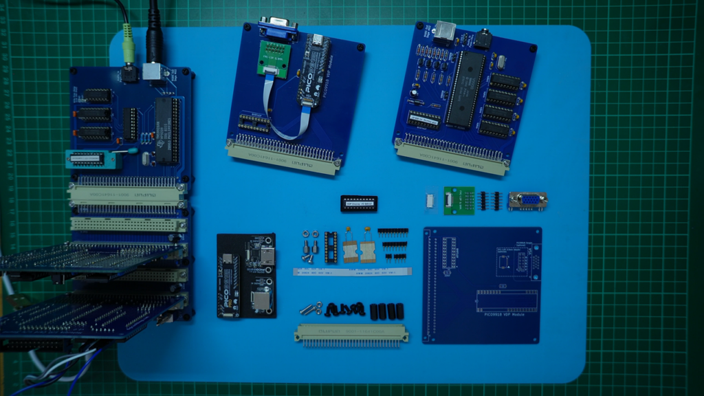
So, on my workbench (below), you can see all of the components required to make up my MECB PICO9918 VDP Display Card. Including my own purchased PICO9918 module and some output “dongles”.
MECB PICO9918 VDP Display Card Output Options
Now, for the MECB Kitset itself, there are a few options to consider.
Firstly, if wanting a VGA output, you could choose to do some fine surface mount soldering work, by soldering the 0.5mm pitch display cable connector directly to your PCB.
Or, if like me, you prefer through-hole ease of assembly, you can select to instead use the FFC Adapter board.
If you choose the surface mount connector, this also frees-up the RGBHV VGA header, if you wanted to mount your own VGA socket on a case (for example).
Of course, for mounting a VGA connector on a case you also have the option of using Troy’s VGA dongle, together with a longer Flexible Flat Cable (FFC), to connect it directly to the PICO9918 module itself.
Otherwise, you can choose to solder the provided optional Onboard VGA Connection Pack‘s VGA connector directly to the PCB, and use the RGBHV header for mounting the FFC Adapter board.
As you can see, in the above workbench photo, I did this on my original MECB PICO9918 Card (which I’ve used since last year).
In addition, if you prefer to use the HDMI or RGB output connector dongles (which can be ordered from Troy, along with the PICO9918 itself), then one of these can be mounted directly onto the PCB mounting holes, using the PCB stand-offs (which I provide in the Component Pack).
However, a HDMI or RGBS output approach doesn’t need the FFC Adapter board, or the header strips, or the VGA connector!
In other words, it doesn’t need my optional Onboard VGA Connection Pack.
Here you can see a visual MECB kitset summary of the optional packs available.
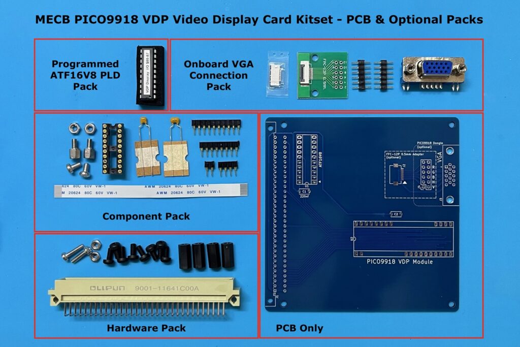
So, you have plenty of choices, which gives you plenty of flexibility with choosing your desired video output connection.
Currently, I’ve already got my original v1.0 MECB PICO9918 VDP Display Card with onboard VGA, which I’ve been using since last year. So, it’s now time to make an updated v1.2 MECB PICO9918 VDP Display Card with HDMI output.
MECB PICO9918 VDP Display Card Assembly
Let’s assemble my latest v1.2 PCB, with my new PICO9918 Pro, and an HDMI output dongle.
Be sure to watch the linked video, where I walk through the assembly.
Alternatively (to summarise) …
I start with the bypass capacitors.
Next, I solder the 20 pin DIP socket for our PLD.
Next, the four single in-line header socket strips, for the PICO9918 module.
Finally, our DIN 41612 bus connector, which I also bolt to the PCB with the 10mm M2.5 bolts.
As I won’t be using the Onboard VGA Connection pack, I remove those parts from my workbench.
Instead, I’m using the HDMI dongle supplied by Troy.
So, I bolt in the stainless-steel PCB stand-offs, which I supply in the component pack.
Next, I screw-in the four nylon PCB stand-offs, to allow the PCB to be nicely supported. This is because I’ll be temporarily inserting it into the MECB Backplane’s horizontal DIN connector.
Now, with the PCB ready to go, it’s time for me to plug in the PICO9918 Pro module.
Then, I firmly mount the HDMI “dongle” on to the PCB stand-offs, using the stainless steel M3 nuts.
Finally, I connect the module to the HDMI dongle, with the 10cm FFC cable (which I include in the component pack).
This just leaves the PLD chip for our memory map glue logic.
Okay, summarisation of assembly complete! However, I’m sure the visual assembly (shown in the video) is more infomative. 🙂
MECB PICO9918 VDP Display Card Operation
With the MECB PICO9918 VDP Display Card now basically fully assembled, just requiring a PLD chip, let’s take a look at its operation.
The simplest real-world usage test is to use my 6502 based CreatiVision re-creation.
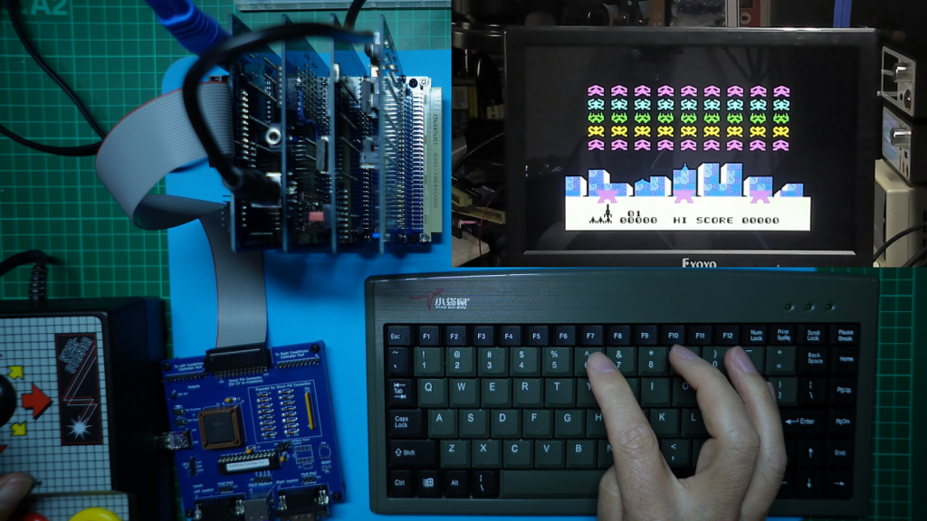
So, first I’ll get my CreatiVision up and running with my favourite original Sonic Invader cartridge game.
PICO9918 HDMI and RGBS “dongle” Pass-Through Audio Connection
However, before I dive into Sonic Invader, I’ve just realised that I forgot the audio connection.
Both the HDMI dongle and the RGBS dongle (supplied by Troy), come with a fly-lead and connector for supporting the pass-through of audio.
Either via HDMI, or via the audio pins on the RGBS mini-DIN connector.
This is similar to the Audio Pass-through inputs which I provide on both my TMS9918 family and V9938 VDP cards. On these existing cards I provide the choice of a stereo audio 3.5mm phone jack connector, or, a PCB mounted header, for the Audio Pass-through input.
However, Troy supplies a fly-lead, with it’s associated connector, for optionally mounting it on the HDMI or RGBS dongles.
So, I’ll just quickly pause to get that connector soldered in place. I’ll also terminate the supplied fly-lead with a 3.5mm phone jack, so that I can easily patch across the sound output from my Motorola I/O Card (with my 3.5mm to 3.5mm audio lead).
So, with that now done, I’ll return return to our CreatiVision re-creation demo.
CreatiVision re-Creation Video Output Demo – Setup
Using my MECB 6502 CPU Card, I’ll first configure it with the CreatiVision memory map glue-logic PLD, and I’ll also install my favourite “Sonic Invaders” game ROM.
So, firstly, I’ll get this operating with my original TMS9928 and TMS-RGB module based VDP Display Card, which you can see in my desk workspace photo above I already have plugged in to the backplane horizontal connector.
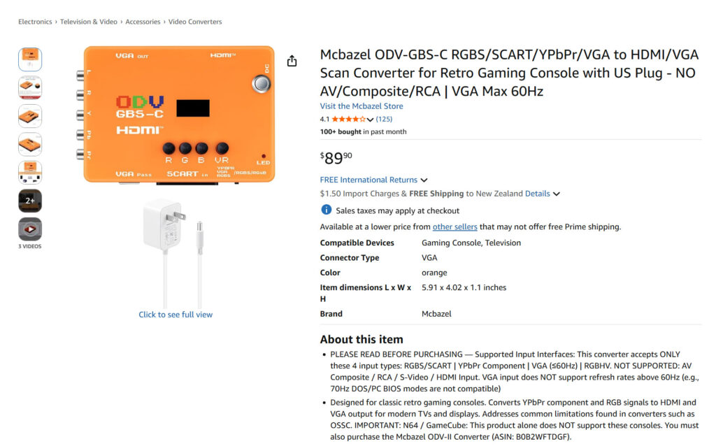
This VDP card uses the TMS-RGB module, to deliver a relatively clean RGBS signal to my external GBS8200 RGBS to VGA convertor, which then VGA connects to my monitor, and the converter’s HDMI output connects to my capture card.
As mentioned earlier, below is the GBS based RGBS convertor, which I’m currently using.
You may also be interested in the more compact solution of a direct Mega Drive 2 to HDMI convertor, which I also regularly use.
It works extremely well, and is a more compact solution.
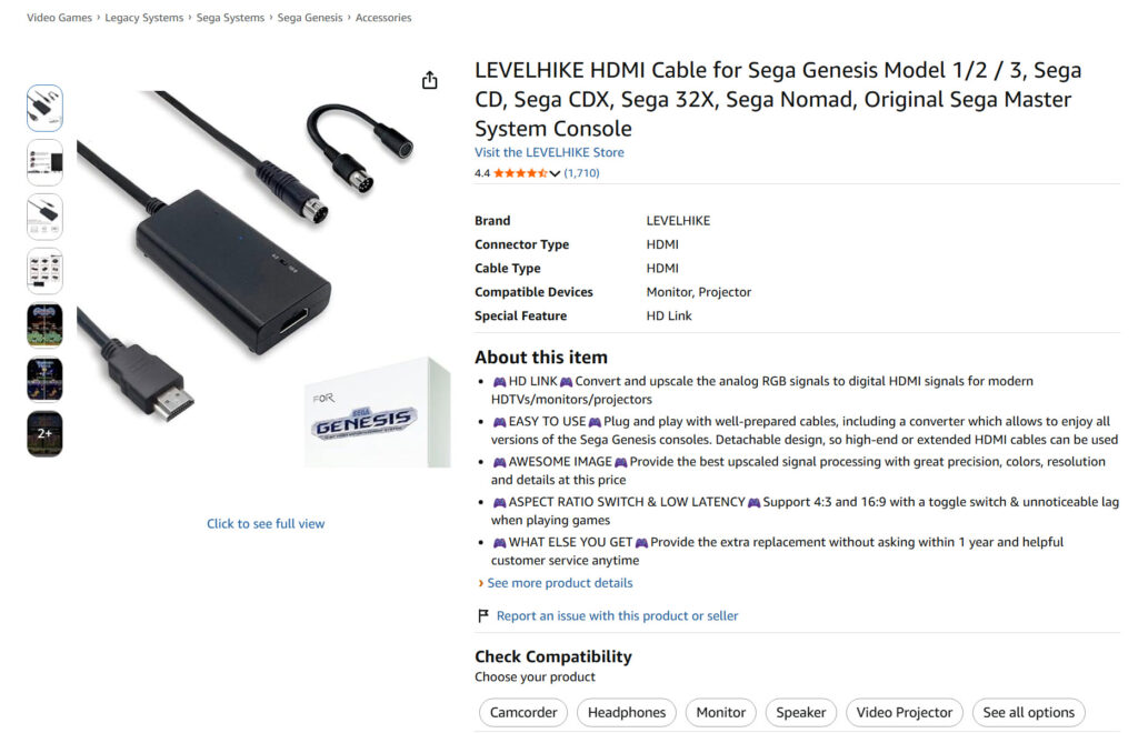
The only downside with these external convertors, is that they both require external power connection, and they are (of course), another device that you need to connect-up.
My issue with the existing PICO9918 RGBS “dongle”
Just before I continue, I’ll mention an issue that I have with the existing PICO9918 RGBS dongle, which is what I was referring to earlier, when I said more on the RGBS dongle later.
Troy has chosen to go down the Sega Saturn 10-pin Mini-DIN connector route, whereas with my existing MECB VDP Cards, I’ve gone with the more commonly available Sega Mega Drive 2 (or Genesis 2), 9-pin Mini-DIN connector solution.
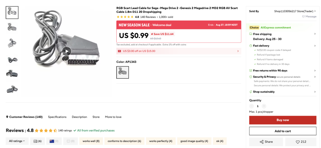
My MD2 choice was mainly driven by two factors. Firstly, the common and cheap availability of Mega Drive 2 RGB SCART leads.
Below is one from AliExpress, for example.
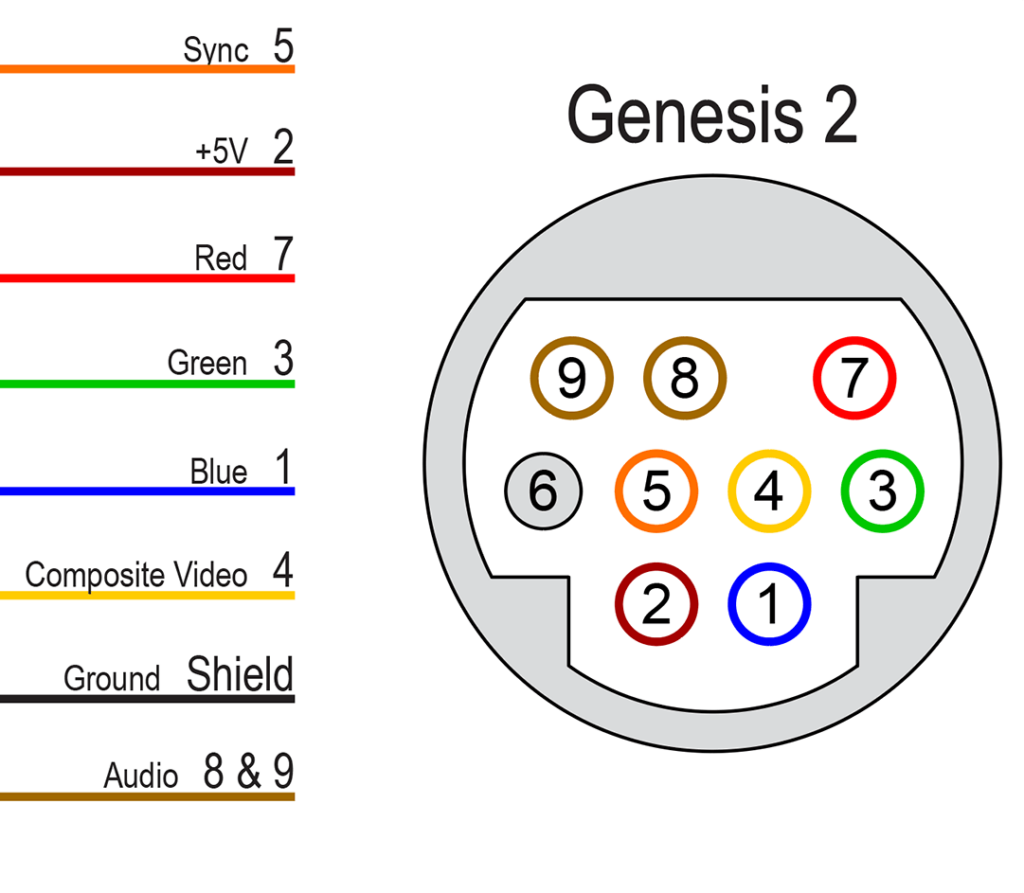
Secondly, the Mega Drive 2 uses a non-proprietary, industry standard, 9-pin Mini-DIN connector, which is also commonly available for “Makers” wanting a 9-pin Mini-DIN output connector
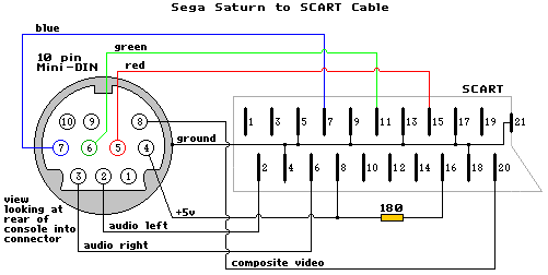
Troy’s RGB output dongle choice was the Sega Saturn 10-pin connector. However, unfortunately, the Sega Saturn uses a proprietary connector, which is not compatible with a standard 10-pin Mini-DIN connector.
Below is a diagram of the Sega Saturn’s connector pin-out.
And below is my PICO9918 RGB dongle, which I bought from Troy.
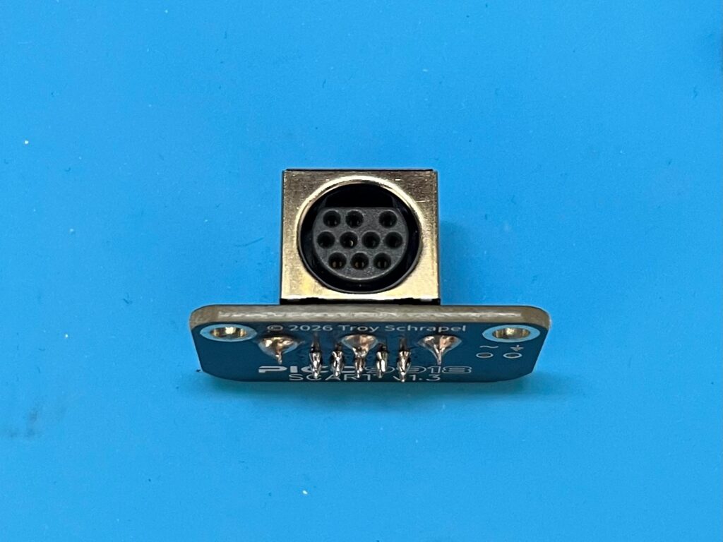
Now, as you can probably see, the standard 10-pin Mini-DIN socket (which Troy has used), is not actually physically compatible with a typical Sega Saturn RGB lead. The flat part of the connector is on the wrong side!
I understand Troy is investigating a better RGBS solution.
My hope is that he’ll instead choose to use the industry standard Sega Mega Drive 2, 9-pin Mini-DIN connector, as I’ve used with my other MECB VDP Cards. It’ll then be compatible with the existing MD2 leads and connection options, which I showed earlier.
CreatiVision re-Creation Video Output Demo – Output
Okay, so let’s get back to the main topic. I was about to take a look at how my existing TMS9928 based MECB VDP Card looks, via it’s RGBS SCART connection, through my GBS to HDMI convertor, and my HDMI video capture.
So, below you can see what that looks like.
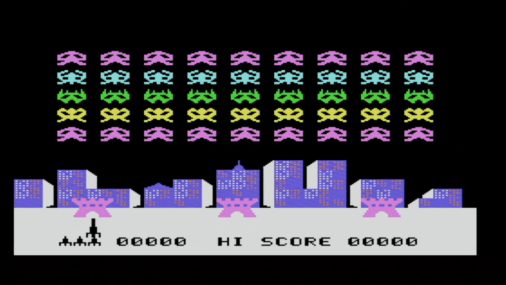
With the TMS-RGB module, the display is really nice and clean, at least when compared to the original Composite Video (or even worse, RF), which we were originally used to with our retro console systems.
Okay, so now I have my new PICO9918 Pro based, latest v1.2 PCB based MECB VDP Display Card, which I just assembled with the HDMI output dongle option. So, no external adapters are required!
Let’s get that connected, so we can see what it looks like.
First, I’ll swap over the CreatiVision VDP memory decode PLD (taken from my TMS9928 VDP Card), onto our new PICO9918 VDP Card.
Next, I’ll plug in my direct HDMI capture cable. No adaptors needed!
Okay, let’s see what that looks like.
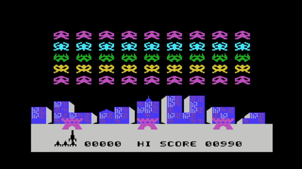
Amazing! I think this represents the ultimate clean & sharp VDP display output, for your HDMI input display, that I’ve ever seen.
Although, it’s also fair to say, that if you’re using a VGA input capable display, then the VGA connection option provides, more-or-less, the same clean and sharp display.
Still useful to have an existing “original silicon” VDP Display Card
Now, before I continue, as I mentioned earlier, also having an existing, original silicon chip based VDP Display Card, is still quite useful. Especially for us enthusiasts, and retro hardware or software developers.
Specifically, I’m referring to my existing TMS9918 or my existing V9938 based VDP Display Cards.
The reason is that (as we all know), when something doesn’t work, we software developers are quick to blame the hardware!
Similarly, we hardware developers are quick to blame the software, when something doesn’t work.
So, when dealing with a hardware replacement solution (like the PICO9918), having an original silicon-chip based alternative Display Card available (to swap out), provides us with the perfect answer to this “software or hardware blame” dilemma.
Therefore, when you are developing code for your VDP display, and things are not working like you think they should, a quick VDP Card swap will immediately confirm that your issue is with your own code, and not with the PICO9918’s implementation of the original VDP hardware functionality!
PICO9918 Advanced Functionality (beyond TMS9918 replacement)
You should also be aware that the PICO9918’s ability to replicate the TMS9918 family, is just the beginning of its capabilities.
As mentioned earlier, the PICO9918 is also capable of more advanced functionality, including emulation of the F18A enhancements. Also, I believe that full V9938 compatibility (and, who knows, perhaps even V9958 compatibility), is also in Troy’s future development plans.
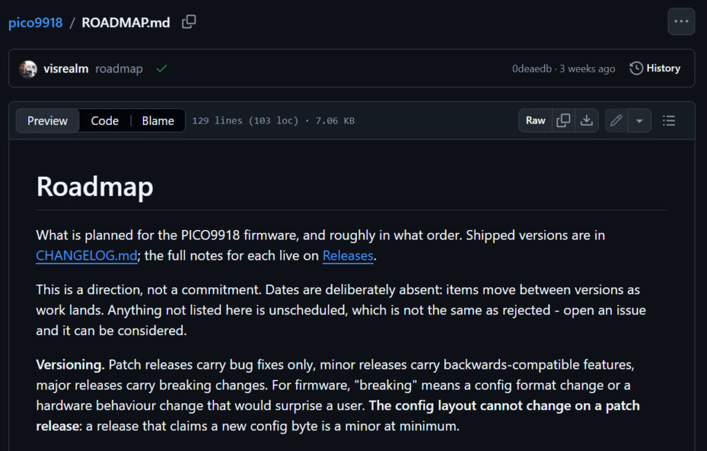
Troy also provides a published PICO9918 Roadmap with his future PICO9918 development plans (as below).
PICO9918 “Sprites per Scanline” Enhancement Options
Okay, I’ll shortly demonstrate the 80 column text mode functionality, which is one of the enhancements beyond the original TMS9918 capability.
But, another enhancement example, which I’ll share, is with regards to the number of supported Sprites per Scanline.
The original TMS9918 family only supports a maximum of 4 sprites per scanline.
If a 5th sprite occurs on the same scanline, it not only isn’t displayed, but a flag is also set in the status register, to alert the program that 5 or more sprites are currently on a single scanline.
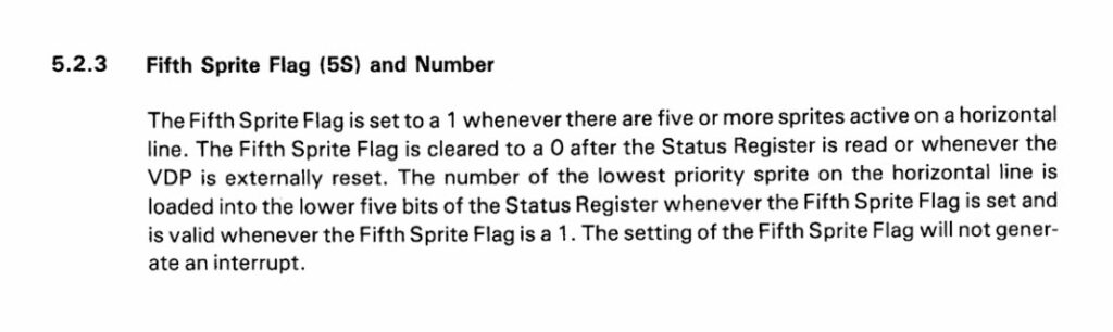
The PICO9918 both supports the correct 4 sprites per scanline limitation of the TMS9918, but also allows resolving this limitation, by allowing 8, 16, or even 32 sprites per scanline.
This is where the PICO9918 Configurator comes in!
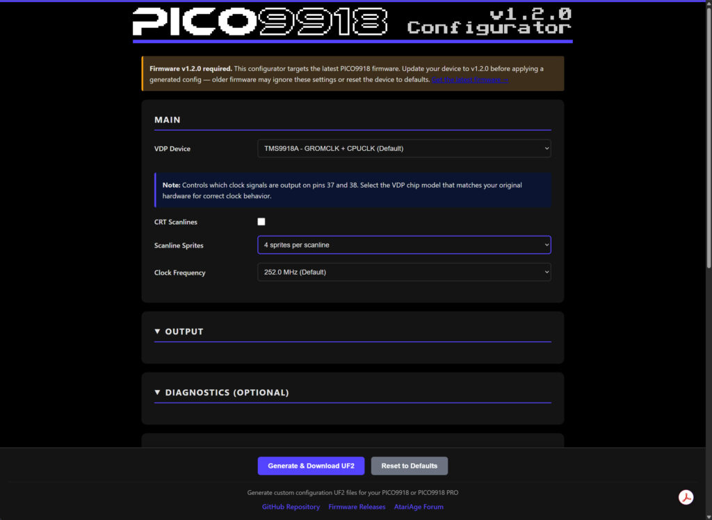
The PICO9918 Configurator allows you to modify the behaviour of your PICO9918 on power-up.
With the default configuration, you power-up in full TMS9918 compatibility mode.
But, via the configurator, you have the power to modify several aspects of the PICO9918 behaviour.
One of these aspects, is the number of Sprites allowed per Scanline.
This does actually provide a good example of an issue, which I thought that I had. Which (of course), my first reaction was to blame the hardware!
To explain, I just previously showed you a HDMI capture screenshot of the original CreatiVision Sonic Invader code running flawlessly on the PICO9918.
But, at one point, I had a configuration in my PICO9918 which allowed more than 4 sprites per scanline.
I’ll show you what happened on Sonic Invader (below).
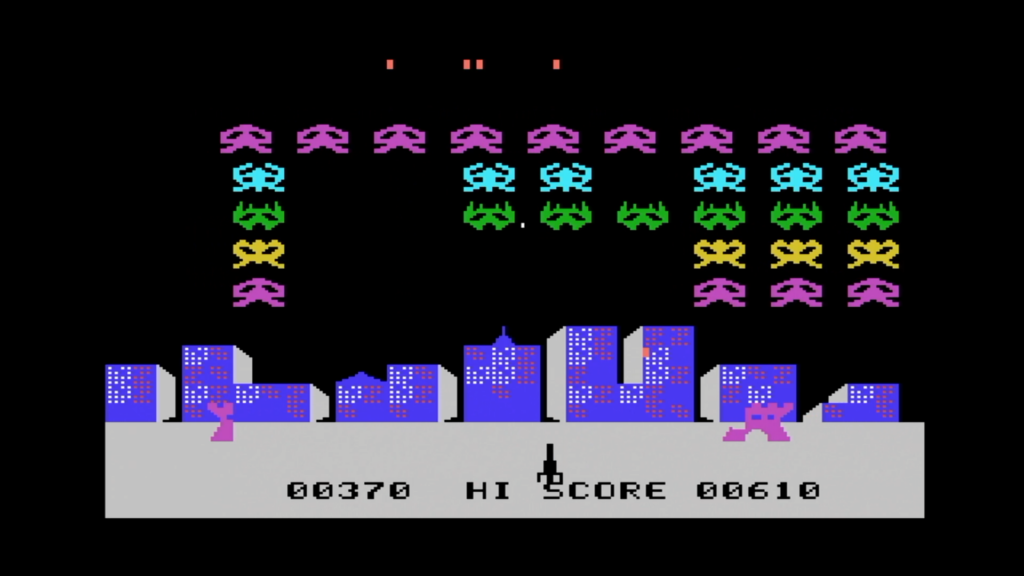
As it turns out, the original Sonic Invader code actually relied on the 4 sprites per scanline limitation, which is inherent in the original TMS9918 family of VDP chips.
I, initially thought that I had found a bug in the PICO9918 implementation!
But, thanks to Troy’s prompt and helpful support, the issue was identified as actually my own PICO9918 having been enabled for more than 4 sprites per scanline.
The quick, and simple, solution, was therefore to simply revert the PICO9918 configuration, back to the correct TMS9918 compliant 4 sprites per scanline maximum (via the configurator)!
Of course, this was only an issue that I had noticed when running the original “Sonic Invader” code for the CreatiVision.
Many other original TMS9918 authored games do not rely on the 4 sprite limit of the hardware, in order to play correctly. Therefore, many other original games are likely to be un-effected by an expanded number of sprites per scanline setting.
TEXT mode and enhanced TEXT 2 mode (80 columns)
So, having earlier demonstrated the CreatiVision Sonic Invader code running perfectly on the PICO9918 display card, I thought I’d also show you my simple 6809 based “Hello World” text output test programs, which I had previously used for testing my MECB V9938 VDP Display Card.
So, to get setup for this I’ll swap-out my MECB 6502 CPU Card for my MECB 6309 PLCC CPU Card.
I’ll also, swap out the glue-logic PLD’s on my MECB PICO9918 VDP Display Card, and on my MECB Motorola I/O Card, so that I have my standard Motorola ASSIST09 monitor based memory map.
Okay, so firstly, we have the TMS9918 backward compatible original 40 character text mode.
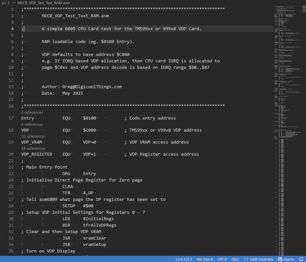
Note that the full assembly source code for these tests, is available on the MECB Github (if you want to replicate this).
Let’s take a look at it running, with a full screen HDMI frame capture.
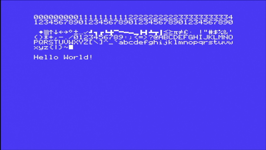
Next, we have the V9938 (and also F18A compatible) enhancement of providing the full 80 column TEXT 2 mode.
Lets take a look at that.
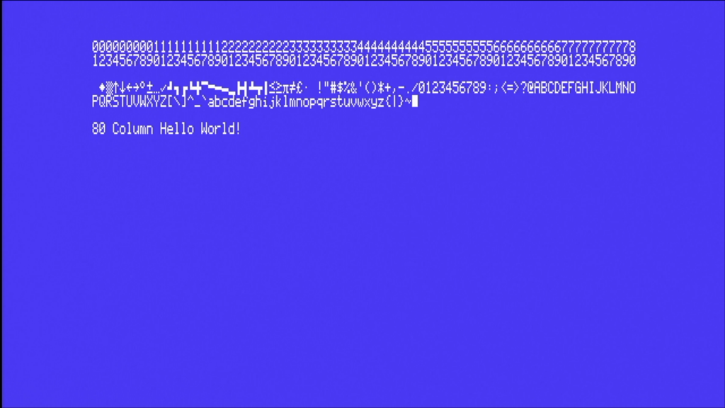
The key thing here is just seeing how clear & readable the 80 column text mode is. This is enabled by the clean and sharp PICO9918 display output.
I’ll also note that the scaled screen frame captures (shown above), don’t actually do it justice. Viewing it first hand, the screen is pixel sharp!
PICO9918 Programmers Reference Guides
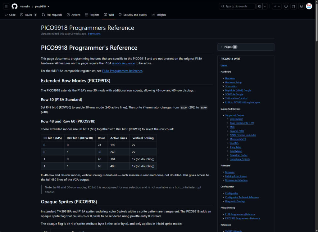
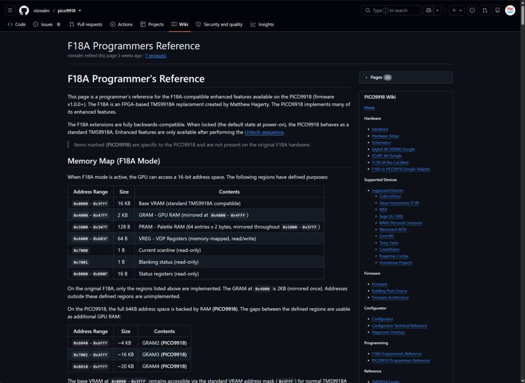
Now, for you to really take advantage of the PICO9918’s capabilities, with your MECB system, beyond it’s simple TMS9918 replacement use, there is a couple of excellent Programmers Reference wiki pages that Troy maintains on his Github Wiki.
Firstly, the PICO9918 Programmer’s Reference
Secondly, the F18A Programmers Reference
These guides, combined, give us plenty of advanced capabilities to play with.
Future of retro VDP Display based fun!
So, if you’d like to experiment with the future of retro VDP Display based fun, then be sure to visit my online store and take a look at the MECB PICO9918 VDP Display Card, together with Troy’s PICO9918 module offerings.
And, don’t forget, my original silicon based VDP Cards are also still available.
Having one of these original VDP cards to hand, alongside your PICO9918 based card, really sets you up for lots of VDP based coding confidence, and experimentation!
As usual, resources can be found on the MECB Github.
Have fun.