- Introduction
- Update – Mon 30 Sept
- Update – Mon 7 Oct
- Update – Mon 14 Oct
- Update – Mon 21 Oct
- Update – Fri 25 Oct – Crossing the finish line!
- Discussion
Introduction
So, after my last project, I’m actually itching to get back to my growing MECB related project list.
But, I’m also keen to round-out my CreatiVision Controller journey, with my envisioned CreatiVision Keyboard.
This would provide a nice mechanical Keyboard add-on to my just finished CreatiVision Controller project, and also to satisfy my “job fully done” mentality.
It will also deliver on the “one more thing…” teaser, that I included at the end of my CreatiVision re-Creation (Part 2) video.
So, to nudge me in the direction of completing this additional CreatiVision related project (before getting distracted by another exciting MECB project), I’ve entered my intentions into the RetroChallenge 2024/10 competition.
Well, I don’t really view it as a competition entry though, more a case of: “Tell someone else about your plans, to put more pressure on you actually carrying-through with those plans!“.
Therefore, I’ve also created this Blog post to track my progress on this project.
My intention is to update this post, as I progress through my CreatiVision Keyboard project milestones.
So, there you have it. I guess that means my main October 2024 project is going to be my mechanical CreatiVision Keyboard add-on to my recently published CreatiVision Controller.
Update – Mon 30 Sept
Well, October is almost upon us. So, as my first blog update, for RetroChallenge 2024/10, I thought I’d give some background, and set the starting position for my October endeavours!
At the end of my last video I feature a teaser of my intended CreatiVision Keyboard project, by showing the keycaps that I’d created, alongside an image of the official (and now hard to find), “moving key” CreatiVision keyboard accessory.
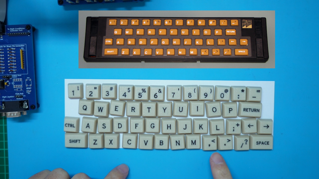
As you can see, my new keycaps have key legends that exactly match the legends on the original keyboard accessory.
There is a bit of a back-story to the creation of these keycaps…
I have some history with designing 3D printed keycaps, as I’d gone through a significant amount of experimentation & tweaking when creating my existing Cherry MX based Hexadecimal Keypad project.
In fact, my dual-colour Hex keypad keycaps only became possible to create (with the finish quality that they have), after I had upgraded my 3D Printer to the Bambu Lab X1C. If you have watched my Hexadecimal Keypad project videos, you’ll note the Cherry MX version of my keypad was on hold for a couple of years, after I had tried several solutions which I wasn’t happy with!
Ultimately, they were printed using the Bambu Lab X1C AMS, for multi-colour printing capability, creating very nicely detailed embedded second-colour key legends, using the printer’s standard 0.4mm nozzle.
The CreatiVision keycaps, however, added a new level of detail that was required from the 3D Printing. This is because my existing Hex keypad only required a single key legend on each keycap. Whereas, the CreatiVision keyboard has shifted key legends, requiring smaller characters for the legends, to allow fitting two legends on a keycap.
This required going to a smaller font, in some cases the characters needed to go down to just 2.8mm font height. That’s half the font height I was using for my Hex keypad!
Some experimentation showed that this was beyond the capabilities of a 0.4mm nozzle 3D printer, even with the amazing quality the Bambu Lab X1C printer was capable of producing.
So, it was time to go to a super-fine 0.2mm nozzle. This was actually a real eye-opener for me, as I’d not previously tried the smaller nozzle. Yes, as it turned out, I was truely blown away by the fine print detail that the 0.2mm nozzle was capable of producing. In fact, I was so impressed, that I no longer have any desire to own a SLA printer for fine model printing!
Now there is one downside to using the 0.2mm nozzle. That is, that the print speed is relatively slow. It takes approximately 4 – 5 times as long to print a model, as it does to print the same model with a 0.4mm nozzle! But, if you’re printing small models, this really isn’t a big problem.
Not to stop there! I also decided to further research the font that I was using for my 3D printed legends. This research also led me to a further quality improvement in my finished result, changing to a font that my research determined was the best font to use for 3D printed font applications.
So, after a series of test prints, to optimise the character height for each of the different key legend characters, I ended up with the 48-key CreatiVision keycap set pictured above. And, I must say, I’m really impressed with the final quality of these keycaps. I’ve even printed them in my “Retro-beige” colour, which I also offer with my MX Hex Keypad. “Retro-beige” appeared to be the perfect colour option for a CreatiVision MX keyboard!
This success was all that I needed to convince me it was worth progressing with my envisioned MX keyswitch based CreatiVision Keyboard add-on, to my just completed CreatiVision Controller project.
Hence, I was all set for an October project challenge. Tomorrow is October 1st, so let’s get started!
Update – Mon 7 Oct
To kick-off this CreatiVision Keyboard project, I decided that the first logical task was to do some work on proving that I could get some of my planned Keyboard firmware operational.
The intended firmware can be split into two distinctly separate primary functions.
Firstly, there is the need to scan our keyboard matrix, detect any keyswitch state changes, debounce the keyswitch state changes, and finally determine the resulting scan codes that we want to add to our scan code buffer.
Secondly, and separately, we need to take any scan codes, that are in our scan code buffer, and send them out the PS/2 port.
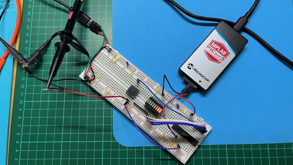
So, to get started, I decided to hook-up a microcontroller on my breadboard, with one of my 8-bit LED Things, for some visual debugging.
I also decided, for retro appropriateness and Through-Hole (TH) friendliness (and, also for convenience), that I’d use the same 8-bit AVR microcontroller which I’d used for the CreatiVision Controller design.
I could use the same PORTF pins for the PS/2 interface, then use the two 8-bit ports, PORTA & PORTD, for a 8 x 8 matrix keyboard array.
This just left the 4 available pins of PORTC unused, PC0 – PC3. So, I decided to wire them up to four LEDs on my 8-bit LED Thing.
I then grabbed a spare 12x12mm Tactile Switch, inserted it into the breadboard, and then hooked it up between PORTA and PORTD. For an initial switch test, I connected it between the PA0 and PD0 pins.
With this all setup, I was ready to start on the first function of the Keyboard firmware.
Note that, as with the CreatiVision Controller project, I decided to start from scratch with the code. Although keyboard matrix scanning algorithms have been done countless times before, sometimes you just want to do it your way. So, with that thought, the wheel is once again re-invented! LOL
Next, I wrote some code to do a full 8 x 8 matrix scan, also implementing a debounce delay scan count, and then finally outputting PS/2 scan codes to a circular buffer, upon each verified key state change.
A key-press would generate the key’s matrix position scan code, and a key-release would generate the release scan code 0xF0, followed by the key’s scan code. In total, three scan codes (one on press, then two more on release), should be added to the scan code buffer, for each button press and release.
If we had key-bounce issues, then we would see more than three scan codes added to the buffer. Likewise, if the firmware code wasn’t working as intended, we’d probably not see any scan codes at all!
So, to visually test this, in the simplest way possible, I just created a main loop where I repeatedly called my keyboard scanning routine, followed by outputting the current buffer scan code count on PORTC (which is connected to the first four LED’s of an 8-bit LED Thing).
This all worked to plan, and you can see in the photo below the LED showing a count of 3 after a button press and release. i.e. 0b0011 (binary).
I also used an oscilloscope to monitor proceedings, tweak my debouncing (for consistent reliability), and I also tested with many many keystrokes, to ensure every key-press generated exactly one entry in the scan code buffer, and every key-release added another two.
Nice!
So that was the successful completion of my keyboard matrix scan firmware development & testing, which consumed last week’s time available for me to spend on this project.
For the coming week, I should next work on implementing the second function of the firmware, and also make a start on my Schematic (now that I know the firmware is showing promise!).
Update – Mon 14 Oct
For week 2 of my CreatiVision Keyboard project, to follow-up on week 1 (where I successfully implemented my initial key-matrix scanning firmware), I decided to next work on the second half of the PS/2 keyboard firmware.
That is, the PS/2 output of any scan codes that are contained in my scan code buffer (having been deposited there by the key-matrix scanning routine).
Research told me that the PS/2 keyboard clock frequency should be in the 10KHz – 16.7KHz range. Therefore, I decided to setup a hardware timer to create a regular interrupt heartbeat, which I configured for a 35us interval.
To initially test this regular interrupt, I just created a very simple Interrupt Service Routine to simply toggle a PORT output pin, upon each interrupt call.
If this was working correctly, I’d then see a nice 50% duty-cycle ~14.3KHz square wave (i.e. a 2 x 35us clock cycle), coming out of the PORT pin! This obviously would then form the basis for a PS/2 keyboard clock within the aforementioned 10KHz – 16.7KHz range.
This all worked to plan!
So, the next step was to implement the code required to use this interrupt, to actually clock-out any scan code that was available from the buffer.
In doing so, I also calculated the required odd parity bit, and I also allowed a reasonable period (count of interrupt cycles), between each scan code transmission.
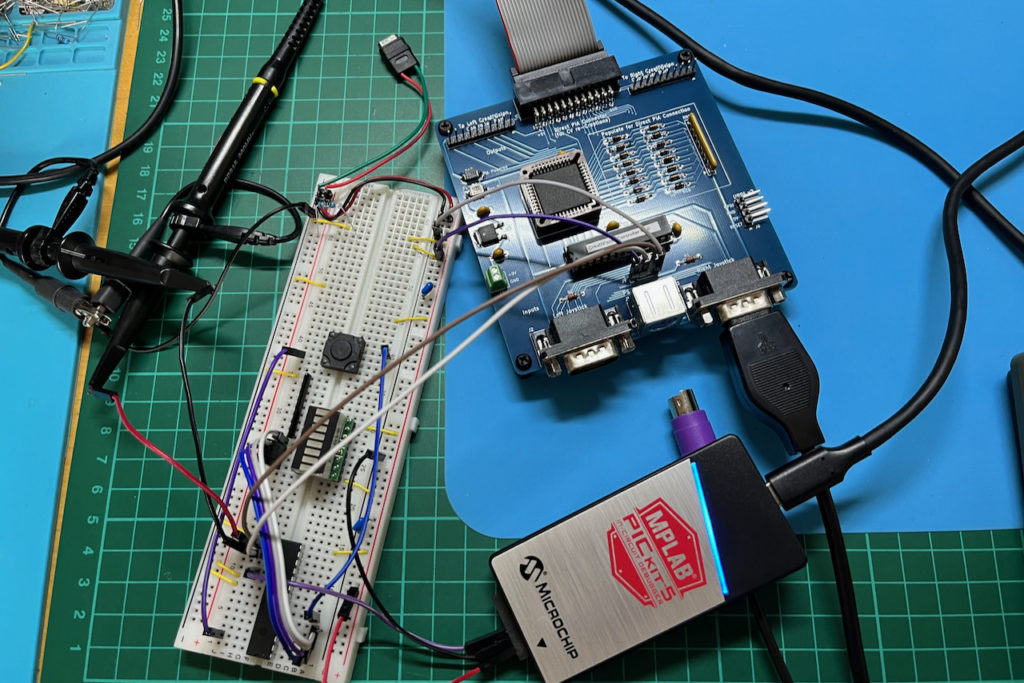
To test this second part of the firmware, I went back to my breadboard circuit (that I’d used last week), and just linked-across my microcontroller PORTF PS/2 output pins PF0 and PF1 to the PS/2 header on my existing CreatiVision Controller (in place of the previously connected PS/2 keyboard).
With everything connected, and my MECB CreatiVision re-Creation up-and running, I was then able to check that when I pressed my test Tactile switch (on my breadboard), that the programmed scan codes were being sent correctly to the CreatiVision, as the expected PS/2 keyboard transmission.
This test setup can be seen in the photo below. You’ll also note that the breadboard test circuit is now being powered directly from the PS/2 header connection, just as the final keyboard will be.
With this functionality successfully coded and tested, the full firmware requirement capabilities for my chosen microcontroller, were now proven.
It was now time to formalise the CreatiVision Keyboard’s schematic.
For the keyboard matrix I decided that, since the original CreatiVision controllers utilise a 6 x 4 keyboard array for each of the left & right controllers (to provide two 24-key halves of the full 48-key keyboard), I’d follow this as a matrix layout to effectively create a 6 x (4+4) matrix. In other words, a 6 x 8 matrix, for our 48 key keyboard.
However, since we have an 8 x 8 key matrix available, I then moved the SHIFT and CTRL keys out to the, otherwise unused, 7th and 8th rows. This effectively means that these two keys are each allocated their own row.
The reason for doing this is that it minimises the chance of ghost key-presses. A ghost key-press can occur when multiple keys (3 or more), are pressed simultaneously. As SHIFT and CTRL are typically used in a simultaneous key-press operation, moving them to their own row each, minimises the risk of a ghost key-press.
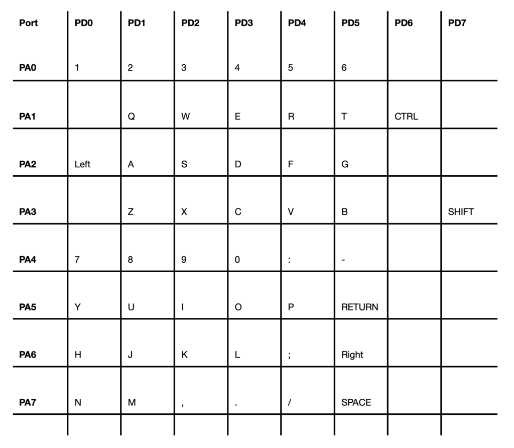
PORTA & PORTD 8 x 8 key matrix allocationsIn addition to defining the key matrix for the schematic, I also decided to add the appropriate open-collector drivers (actually open-drain), to the PS/2 keyboard output circuit. I have done this via a couple of N-channel MOSFETs, with 10K pull-up resistors. Note that this also requires me to invert the output levels of the microcontroller’s PS/2 PORTF pin PF0 and PF1 outputs. No problem. With an AVR, port level inversion is configurable!
Now, for use with my CreatiVision Controller interface, note that open-drain outputs for the PS/2 interface are not actually needed. The CreatiVision Controller’s keyboard port acts as an input only, so there is no conflict by having a direct port-to-port connection. However, I considered that if I didn’t adhere to the correct PS/2 port specifications, I would, no-doubt, regret it later!
So, below we have my CreatiVision Keyboard Schematic, which I’ve come up with, rounding out the 2nd week of effort on this project.
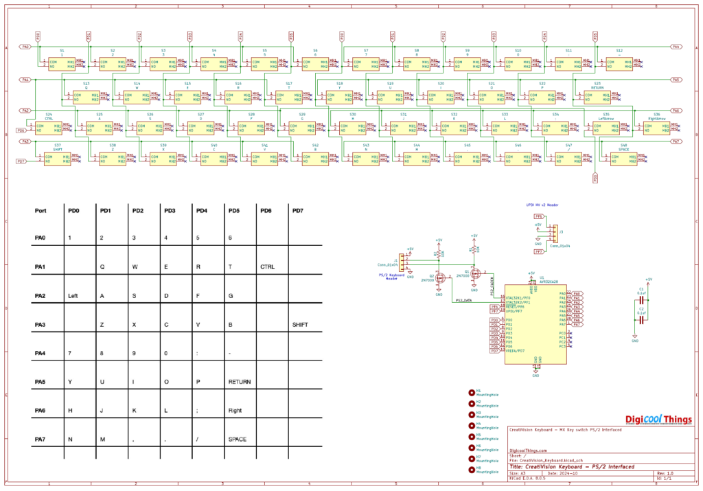
Really exciting! As, here we are in mid-October (half way point?), and I have now written and also successfully tested the functions of the required keyboard firmware, and I have the v1.0 Schematic completed.
For the coming week, it will be time to start designing the PCB!
Before signing-off for this week’s update, I’ll also add that my RetroChallenge project will now become Part 4 in my CreatiVision re-Creation journey (instead of the Part 3 it was originally going to be).
This is because, last week, I’d also been working on (and have now published), a related CreatiVision re-Creation (Part 3) video & blog.
This was actually quite exciting, as it announces a major version upgrade (to v2.0), for the CreatiVision Controller interface, which I had originally released as v1.2 last month. This is, of course, what the CreatiVision Keyboard is intended to plug into!
If you haven’t yet seen this update, you can find it here.
Lastly, there was the pleasing to read “Halftime Update” summary comments from the RetroChallenge team…

Update – Mon 21 Oct
So, for week 3 of my October RetroChallenge project, I’ve focussed on the PCB layout.
During the prior week, the firmware capability was proven, and my v1 Schematic was completed. So, onward with the PCB design it was!
Now, PCB design and layout always takes me longer than it probably should.
This is mainly because I tend to be a bit of a perfectionist, therefore, even when I have completed a PCB layout, I know I always have to sleep on it.
Without a doubt, I wake-up in the morning with the thought of something I’m not 100% happy with, or something I hadn’t previously thought through fully.
Even without any major functional changes being required, I also tend to find some PCB trace routes that I want to “tweak” in the fresh light of a new day.
In fact, the only thing I can guarantee, is that for me a PCB is never “finished”. Even when I finally submit it for manufacture, in the days that follow (without a doubt), I always find a small detail that I want to “tweak”.
Fortunately, these subsequent “tweaks” are usually non-functional in nature, and are just about making things more pleasing to the (my?) eye. Therefore, the “tweaks” usually don’t involve any version number changes! I usually reserve version number changes for minor or major functional changes.
So, for the above reasons, my project effort for the week just passed (week 3), has been almost exclusively on the PCB design.
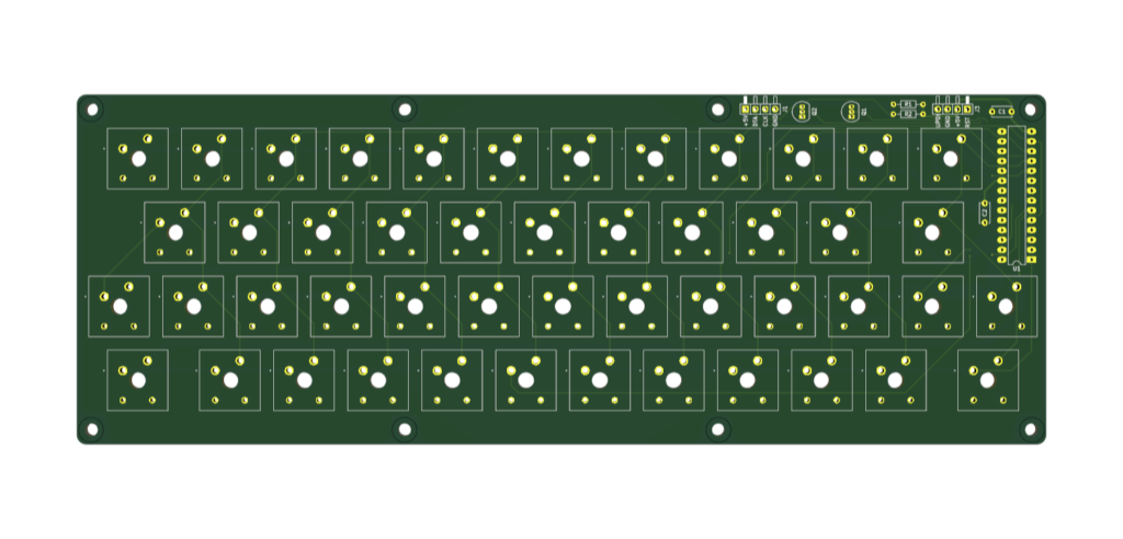
But, I can now report that my v1 PCB design is now complete, and submitted for manufacture.
The below image is a 3D PCB render, so that you can see the final version, as it has been sent for manufacture.
I should also mention that I did spend some time contemplating the thought of splitting the PCB into 3 parts, to allow then to each fit within the 100mm square maximum, for low-cost prototype PCB manufacture.
This would have been achievable, via top & bottom PCB edge pads, to allow solder-joining the 3 segments back into one large keyboard PCB.
But, before I headed too far down this path, I came to my senses!
Just so you know, I did have good reason for initially exploring this option. Not only would it save on PCB manufacture cost, it would also allow me to ship keyboard kitsets in my usual square shipping cartons. However, a full single PCB is definitely the way to go, even at a higher manufacture and shipping cost.
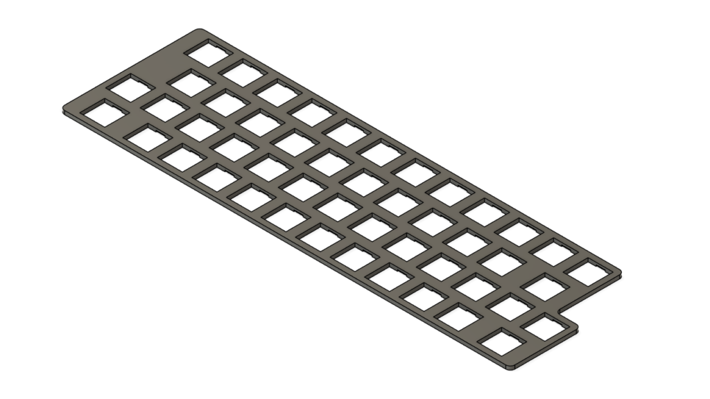
So, with the PCB out for manufacture, the next step was to design a MX key-plate for the keyboard.
As I’d previously done with my Hexadecimal MX Keypad, I designed the key-plate in Fusion, for printing on my 3D printer. A metal key-plate is not really necessary!
Also, as with the keycaps, I included some design enhancements which I’d also evolved (since originally doing my Hex Keypad), for this new CreatiVision Keyboard key-plate.
Below is an image of the resulting key plate.
So, that rounds-out my week 3 efforts on this RetroChallenge project. Again, I’m pretty happy with my progress, with just over a week to go.
Now, for next week, I have to wait for the v1 PCBs to arrive from manufacture.
In the meantime I’ll print some stock of the key-plates (I have confidence no changes will be required for these). I’ll also order some needed parts from Mouser, and also see what further refinements I can make to the firmware.
Until next week’s update…
Update – Fri 25 Oct – Crossing the finish line!
This week, I was mostly waiting for the PCBs to arrive.
In the meantime, I had to place an order with Mouser, for some parts that I needed to complete the Keyboard, and to also make sure that I had stock available for anyone who might like a kitset.
Interestingly, the biggest challenge was determining the correct 2N7000 MOSFETs to order.
Mouser has a number of 2N7000 listings, but none of them specified their case style.
The problem is that there are two different case styles for the TO-92 packaged 2N7000. These are leadformed (case 135AR), and non-leadformed (case 135AN).
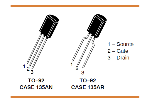
I want the straight-leg TO-92 non-leadformed case (135AN)!
So, after a a couple of support requests, I finally worked out that the “Bulk” packaging listings are likely 135AN, and the “Ammo pack” packaging listings are likely 135AR (leadformed).
I’m still not sure of the case style of the “Reel” or “Cut Tape” packaging listings.
Anyway, with the parts ordered, I then spent a little time on the firmware, and also (as I alluded to in last week’s update), further tweaking my PCB layout. No functional changes, just me needing to make subtle routing tweaks, as a perfectionist (or is it some OCD tendency), always needs to do.
So, by later in the week I had delivery of both, my parts order, and the manufactured PCBs. Awesome!
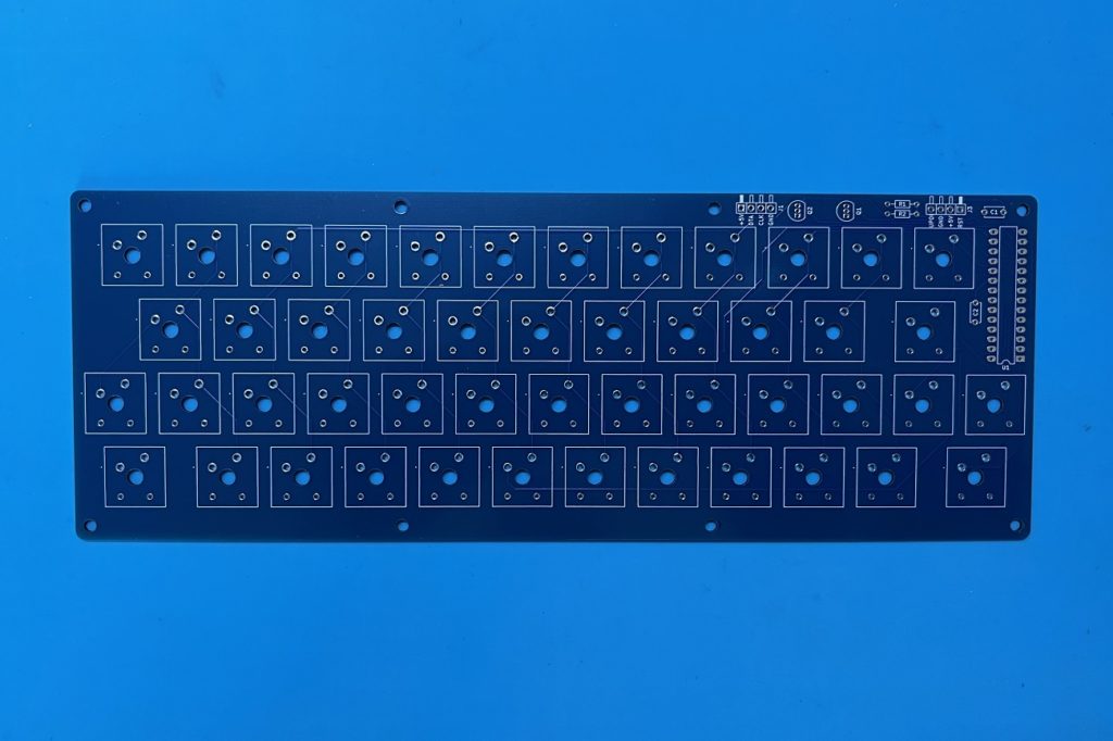
Without any further delay, I dived into assembling my first Keyboard, whilst also filming my assembly journey.
Then, finally, the testing of the first assembled Keyboard.
During testing I found just one coding oversight, affecting the arrow keys. So, I quickly resolved that oversight, culminating in a successful test!
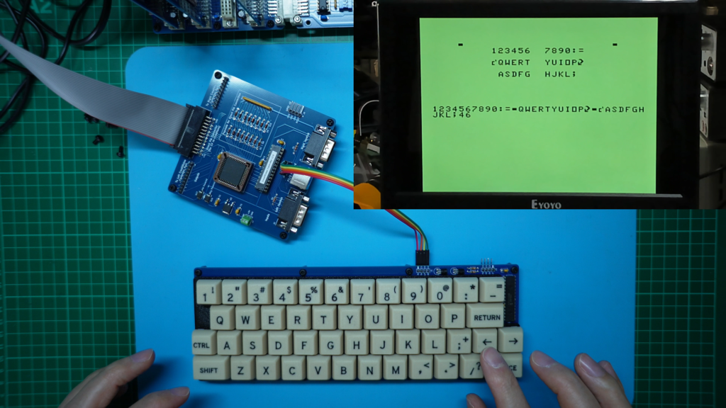
Next, I tasked myself with editing my video sequences into a YouTube video, to present my finished RetroChallenge CreatiVision Keyboard project.
In addition, I also needed to write my CreatiVision re-Creation (Part 4) Blog, to accompany the YouTube video (below).
Then, organising the Tindie Store listing of my new CreatiVision Mechanical Keyboard kitset.
Next, there was the publishing of various project resources via a new public GitHub repository (CreatiVisionMechanicalKeyboard).
Finally (phew), I needed to write this final weekly update to this RetroChallenge progress Blog.
So, all-in-all, a busy week. Which, is as my projects usually go, the final week of a project is usually all about administrative tasks and final tweaks.
In case you missed it, the YouTube video went public today (as I write this), Friday 25 Oct . You can find it here:
Also, don’t forget to browse my Tindie Store. 🙂
So that’s me, all done for the October RetroChallenge 2024.
- RetroChallenge 2024 successfully completed!
- CreatiVision re-Creation series completed!
If you’d like to experience the full CreatiVision series, you can find the playlist here.
Now, I really should get back to my list of MECB projects in waiting.
Thank you for sharing this journey with me.
