
If you’d like one of these Adapters, you’ll find a Kitset or a Fully Assembled & Tested option, on Tindie: https://www.tindie.com/stores/DigicoolThings/
Note: We no longer sell on eBay, as their high fees and forced mutiple exchange rate conversions (with exhorbitant fees), meant it was no longer financially viable to offer via eBay.
Amongst Retro Gaming and Retro Computer enthusiasts, there is often a need to program relatively large 42 pin (and 40 pin) 16bit wide EPROM chips.
Often this requirement comes about due to a need to replace an original MASK ROM in 16bit devices like SNES & Sega consoles, and Amiga computers etc. No doubt, this also applies to various other cool Retro devices from the 16bit era.
There is a popular family of EPROM’s which are fit for this MASK ROM replacement purpose. This family utilise a pin-out that is compatible with MASK ROM’s of the same size, so in many cases they are a simple drop-in replacement.
This popular EPROM family includes:
- 27C400 – 4Mb, organised as 256K x 16bit in a 40 pin DIP
- 27C800 – 8Mb, organised as 512K x 16bit in a 42 pin DIP
- 27C160 – 16Mb, organised as 1M x 16bit in a 42 pin DIP
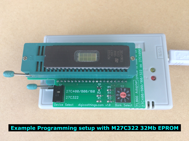
- 27C322 – 32Mb, organised as 2M x 16bit in a 42 pin DIP
EPROM Programming Challenge
The challenge is finding a reasonably priced programming solution for these devices.
Most of the popular “reasonably priced” EPROM programmers only accept devices up to 40 pins. EPROM programmers that support the above family of devices “out of the box” can run into the hundreds of dollars! Not particularly wallet friendly for most Retro enthusiasts or electronics hobbyists!
A good example of a very popular EPROM programmer is the TL866 series of USB EPROM Programmers, which can generally be picked up for a very reasonable price. These have proven very popular with hobbyists. They feature a 40pin ZIF socket, and as at the time of writing (v6.60 software), the TL866 supports in excess of 14,000 devices. Whew! But, not surprisingly, this does not include the above family of devices, as the 42pin devices wouldn’t even fit in the 40pin ZIF socket.
When I needed to program a 27C322 EPROM, I went searching for a method of programming this 42pin chip. Google located an adapter that would work with my TL866, but unfortunately they no longer appeared to be available to buy. I, along with others before me, even posted an expression of interest on the discussion forum, but alas, no response!
TL866 EPROM Programmer Adapter Solution
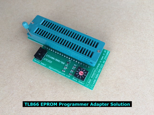
As you may have already guessed, I therefore decided to design my own adapter, from scratch. And, as usual, designing a solution to my EPROM programming requirement was never going to be just a quick one-off breadboard circuit hack. I like to do things properly!
My inner perfectionist also wanted to improve on the unavailable adapter, with which Google had teased me.
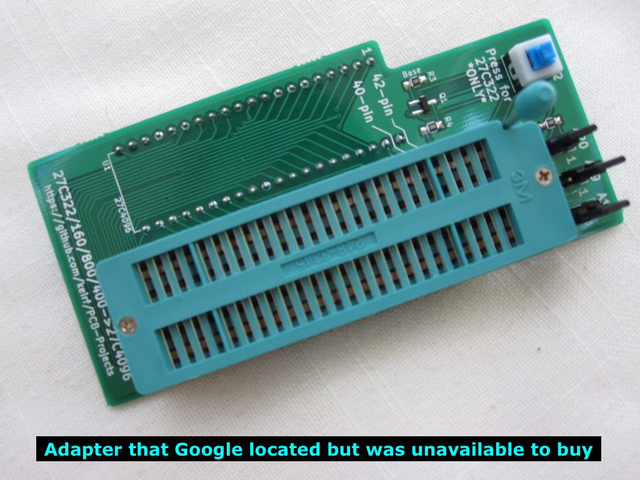
My short list of “issues” with the Google example (which I perceived as unsatisfactory), were:
- Using individual jumpers (or even switches), for toggling the binary address lines (to select the memory bank to program), seemed unnecessarily tedious, non-intuitive, and prone to human-error.
- The use of a push on/off switch for device selection didn’t appear to be the best way to provide a clear visual indication of which device was currently selected.
- I was unhappy with the physically unbalanced design of having the 42pin ZIF socket alongside the 40pin header (not above it). I wanted my adapter to sit nicely balanced in the programmer’s ZIF socket. I didn’t want the adapter to fall over sideways when the programmers ZIF socket wasn’t clamped shut!
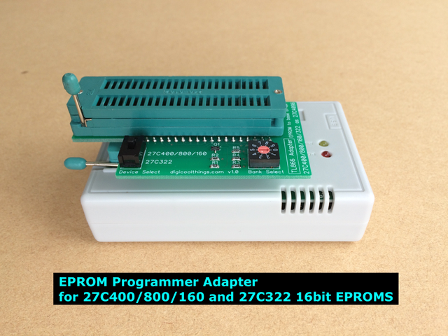
So, after pulling down all the data sheets for the various EPROM’s and drawing up a suitable design, I finally have my improved EPROM Programmer Adapter completed, fully tested, and happily resolving my MASK ROM replacement programming needs using my TL866 EPROM Programmer. 🙂
In resolving the issues I saw with the existing Google located example, my improved adapter implements:
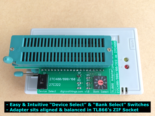
- A simple and intuitive rotary “Bank Select” switch to allow quick, easy, and error free selection of which memory bank to program.
- A clearly labeled slide switch for “Device Select”, to allow easy visual indication of currently selected device.
- The Adapter’s ZIF socket is positioned over the TL866’s ZIF socket allowing it to sit nicely balanced, and with the board edge nicely aligned with the edge of the TL866’s case.
Programming is Easy
Programming is easy. On the TL866 software you simply select the supported 16bit EPROM type 27C4096. This is a 4Mb 16bit device which uses the JEDEC-approved 40pin DIP pin-out (which is not MASK ROM compatible).
You then select the Vpp programming voltage suitable for your chosen EPROM. For my STMicroElectronics M27C322 (32Mb EPROM), I select 12.5v Vpp. Finally, unselect the “Device ID Check” check-box.
If programming a 27C400 (4Mb) you are now ready to go. For the larger devices you’ll first need to use a file split utility to split your EPROM file into 4Mb (512KB) segments, as the TL866 thinks you are programming a 4Mb EPROM (ie. 27C4096). For this I use a free utility called HJSplit, which nicely provides numbered file segments.
You then program each 512KB file segment using the “Bank Select” as follows:
- 27C400 – Single 512KB file, no Bank Select required!
- 27C800 – Two 512KB file segments, use Bank Select 0/1
- 27C160 – Four 512KB file segments, use Bank Select 0/1/2/3
- 27C322 – Eight 512KB file segments, use Bank Select 0/1/2/3/4/5/6/7
I also prefer to select the “Blank Check” programming check-box option, as this makes the whole programming process a one click per bank exercise, with the blank check providing verification that we did remember to advance the bank select switch before programming the next file segment.
In Summary
OK, there you have it. If you also have a need to program these EPROM devices, I’ll be making this digicoolthings.com Adapter available for purchase on eBay.
Finally, although I’ve fully tested with the popular TL866CS USB EPROM Programmer, I’d suspect it may possibly work just as well with other 27C4096 compatible 40pin EPROM programmers out there.
If you’d like one of these Adapters, you’ll find a Kitset or a Fully Assembled & Tested option, on Tindie: https://www.tindie.com/stores/DigicoolThings/
Note: We no longer sell on eBay, as their high fees and forced mutiple exchange rate conversions (with exhorbitant fees), meant it was no longer financially viable to offer via eBay.
I have a TL866 EPROM Adapter for my mini programmer and im trying to program a 2 meg chip. I dropped the adapter on the floor and some pieces fell off i put it back together and now i cant program my MC27160 chip. The adapter will read and blank check the chip with no problems but won’t program the chip ,and i have the chip designated as a AM27C4096 and there are other chip designations such as M27C40001,M27C40002. ect. does anyone have any advise?
Hi, let’s see if I can help.
Firstly, did you mean a 27C160, which is a 16Mib EPROM (1M x 16)? I’m not aware of a MC27160 device?
Also, when you say M27C40001,M27C40002. ect. I think you might have meant M27C4001 & M27C4002?
The M27C4001 is 32 pin 4Mib (512K x 8) and not compatible.
For the Adapter, you just want to select the AM27C4096 (as you have indicated).
And you want to program / read either 27C400 (40 pin), 27C800, 27C160, or 27C322 (42 pin) EPROM devices, or, read the equivalent Mask ROM devices.
Assuming you have previously programmed a chip successfully, before damaging the Adapter. ie. You are using the Adapter correctly…
Then the steps to check are:
1. When you say you can successfully read and blank check the chip, I assume you are therefore reading all ‘FF’?
2. Have you tried programming different 27C160 chips (in case the 27C160 you are trying is faulty)?
3. Do you have a pre-programmed device, or a compatible Mask ROM, that you can attempt to read to check you are reading all the data lines successfully?
Having confirmed the above, then the damage to the Adapter would likely be related to the pins which control programming: Vpp, CE, OE.
Unfortunately you have only said: “I dropped the adapter on the floor and some pieces fell off”?
You didn’t say what pieces fell off.
As *all* of the parts of the Digicool Things TL866 Adapter are soldered into place, it would not be possible for pieces to just “fall off”.
A piece could only really “break off”, and under considerable force (as in, the Adapter being smashed into pieces!).
If your TL866 EPROM Adapter has been broken, you unfortunately may simply need to get yourself another one. 🙁
HI. Thank you for Answering my question so quickly. The pieces that fell off was a piece of metal that looks like its been bent into a 90 degree angel and the lever that holds the chip down so i put that back on i did program a 2 MB game but it didn’t work. Probably because i didn’t program it properly. I went to try and reprogram it again but it wouldnt program the chip i also tried an M27C801 but i still have the same problem and i’ve tried another M27C160 chip but it gives me the same error message I don’t have any of the original mask rom games because i didnt think i would need them but i learned that lesson, Before i tried to make a 2 meg game i made a 1 meg and it works but thats before i dropped it. all the FFFF’s are in place.Here is the error message i got as i went to program the chip
Error
Adress:0x000000
Buffer Data:0xoo4c
Verify:0xFFFF
What is Address,Buffer Data,and Verify. Im still trying to learn and understand how the game making process works……Would somebody from this website have time to teach me everyday?
So, it sounds like you are saying the ZIF socket has come apart (if pieces of metal / lever fell off).
If this is the case, then it is most likely that one of the programming related control pins (I mentioned earlier) are no longer making a connection when clamped in the ZIF socket.
eg. Vpp? (programming voltage pin)
This also assuming that you have been able to successfully read a programmed chip (ie. successfully read data other than 0xFFFF).
For the Error:
Adress:0x000000
Buffer Data:0xoo4c
Verify:0xFFFF
This error is indicating a write failure, at the very first address.
ie. Attempt to write 0x004C to address 0x000000 was subsequently read back (verified) as 0xFFFF (so not programmed! / still in erased state).
So this does support the likelihood that one of the programming related pins is no longer connecting!
First IC pin to check would be Vpp. The other two programming control pins are CE, OE.
Of course, if you were also unable to read the data on a pre-programmed device (can only read 0xFFFF), then it could also be other pins not connecting.
If the ZIF has been broken you’d be best to replace the ZIF.
Thank You very much:)
You’re welcome. 🙂
HI the ZIF socket was still in place or the covering to hold the chip down was still in place it did not fall off. I don’t have a volt tester to test it out but, i think you’re right because i tried an 801 chip with out the adapter and it still wouldn’t program so it maybe the programmer too. The programmer did hit the floor but it didn’t take such a hard fall as the adapter did and it could be because i dragged a .bin file into the open file tab in the mini pro window and i wasn’t supposed to, so with that being said. i think ill get a new adapter. I know someone that can sell me one at a good price because i’m currently unemployed and i am on a budget so i thank you for all of your help…….one more thing. i did do a self test on the programmer and it said everything checked out ok is there another way to test it to see if it will write on a chip?
Hi again. In your earlier comment, you only mentioned that the Adapter had been dropped, not the MiniPro Programmer as well.
You’ve noted that you: “tried an 801 chip without the adapter and it still wouldn’t program”. So this is the first issue you need to resolve!
ie. Before looking at the Adapter, you need to first make sure your Programmer is working! 🙂
It shouldn’t matter how you loaded the .bin file into the Mini Pro software. The important issues is ensuring you can read your 27C801, confirm it is erased (all 0xFF bytes), successfully Program the .bin file data, and also read back the data after the EPROM has been programmed (and confirmed the same checksum as the original .bin file data).
If this does not work, you also need to try other EPROM chips, to confirm if it is a faulty MiniPro Programmer, or a just a bad EPROM chip!
Only when you have successfully completely this (to prove the MiniPro Programmer is still working 100%), can you then check if the dropped / damaged Adapter is still working.
Hi I tried to get the programmer to blank check a M27C801 chip, it wont even do that. ive tried filliping the chip around sooo many times i cant get it to do anything:( im guessing that theres something wrong with the programmer since im new at the game making, maybe i damaged it somehow trying program the firemen game. Im going to get a Multimeter on Friday and test everything ill let you know something on Friday
Note, it’s unlikely that you would damage the Programmer just trying to program an EPROM.
However, it is possible to damage the EPROM chip.
eg. If the EPROM chip is inserted incorrectly in the ZIF socket (wrong way around / wrong position etc.)
Or if you selected a programming voltage that exceeds the EPROM’s maximum Vpp rating. etc.
So make sure you try more than one EPROM chip when testing the Programmer, and take care to ensure correct chip insertion / programming voltages etc.
the problem with For the Error:
Adress:0x000000
Buffer Data:0xoo4c
Verify:0xFFFF
the bin is corrupt you need a clean bin which has been converted with Swap Endian, and if file is bigger than 512kb you will need to split that file into a few segments of 512kb for each bank! also check if check is ticked off as well.
this adapter is the best! thank you..
Thanks for the feedback Nathan! I’m assuming from your comment that your adapter must have arrived already? That was a pretty quick delivery!
Hi i have been trying to program a M27C160 chip on the program adapter ive been through the steps numerous times and i have erased the chips completely but im still getting errors on the blank check and program errors i bought this adapter through an individual so im not sure where it came from but the programmer i have doesnt require a screwdriver to turn the dial and im not sure if the dial is on 0 or six but there is a tiny notch on the dial what number does the notch need to be on?
Hello again. Your last comments (back in July) indicated that your TL866 Programmer was faulty, as you were having the same issues with a M27C801 EPROM (which doesn’t use the Adapter). So you needed a new Programmer.
If you now have a new TL866 Programmer which is proved working by successfully programming your M27C801, and the Adapter (which you had dropped / broken) is still not working after going through all my prior replies (and steps you should follow), then your Adapter must have also been broken when it was dropped. ie. If you’ve exhausted all the earlier suggestions, then you’ll also need a new Adapter.
If you are getting errors on the blank check, an attempt to program the chip will fail. It needs to be verified as fully erased first (all bit’s as 1 / 0xFFFF), as programming an EPROM only changes a bit from 1 to 0.
If the Adapter you have is the genuine item, then the dial shaft has a clear visible groove that runs down the full length of the shaft to indicate the dial position.
When the dial groove is set to position zero (0) the opposite position would be 5. If on yours it’s 6 than that also suggests it’s not a genuine / original DigicoolThings Adapter.
Note that for programming a M27C160 EPROM you would use banks 0 – 3.
Hello,
I recently bought a this adapter and I am really pleased with the build quality and thought which went into the design. Thank you very much DigiCoolThings! Albeit being just a small board, it is -for me at least- a little piece of art!
I successfully programmed a couple of AM27C400 eproms with the newer TL866 II Plus.
I can confirm the adapter is compatible.
The tutorial video on YouTube has been very helpful and the calm and gentle manner of explaining is very appealing.
Funny story: I was sceptical about the proceeding, since the file manager was displaying 524 KB on disk for the BIN file I had to program, but the programmed EPROM was then working as expected.
Dear me, the solution to the mystery was simple. The macOS Finder rightfully thinks it should calculate 524288 bytes as 524 KB! Well, right, 524 KB are 512 KiB, which fits exactly in one bank!
Thanks again DigiCoolThings! 🙂
Thanks for taking the time to post some much appreciated feedback.
I especially liked your reference to the board being a little piece of art. That is exactly how I feel about design and PCB layout.
Unfortunately I’m also a bit of a perfectionist, hence why the board design is now at v1.2. The original v1.0 design worked perfectly fine, but I seem to find the need to make design tweaks and layout optimisations along the way. Although, I think I can now say that v1.2 may be the final form.
I have made some video demonstrating Adapter compatibility and use with the newer TL866 II Plus. I just need to get it edited and posted.
In simple terms, it’s just a case of ensuring you un-check the new “Pin Detect” option in the updated Xgpro programming software.
Your 524KB funny story will always be a source of good debate for us old school types. For me, I will always consider 1KB to be 1024 (ie. 2^10) Bytes. But I also understand when Hard Drives got bigger there was a reasonable marketing argument for quoting KB as a multiple of 1000.
But let’s not re-open that old debate! Enough to say it is confusing (either way), and correctly applying the KB or KiB symbols is indeed the answer for the new century (well, since 1998 it appears). So I must keep reminding myself, 1024 Bytes is now actually 1KiB not 1KB 🙂