
When I started out with creating my MECB platform standard, for retro 8-bit experimentation, I spent some time deciding on the best retro friendly way to implement a flexible glue-logic solution.
At the time, I decided on the ATF16V8 for the standard glue logic PLD for all of my MECB needs, providing a 2K memory addressing resolution.
However, recently, it was brought to my attention that some well known 8-bit retro systems (which somebody might want to re-create), required a finer than 2K address map granularity.
Join me as I present my solution for expanding the standard MECB Card glue logic design standard, to resolve this limitation.
Introduction
Back in the original days, it was more common to create a specific fixed memory map design for your system, using individual logic gate devices.
But I wanted to create modular card designs for the MECB bus, that could be mixed and matched and allow the easy configuration of different memory maps, depending on what our “end system” goals were.
At the time, I arrived at the Atmel (now Microchip) ATF16V9 and ATF22V10 family of programmable logic devices.
These were perfect for the role, as they were the modern variants of PAL devices that were available in the retro time period I was targeting, and they were also still available in their retro-friendly DIL Through-Hole packaging.
In the end I chose to standardise on the smaller 20-pin ATF16V8, for the MECB standard glue logic choice.
This was mainly due to the fact that the lower cost, and also the use of a common 20-pin DIL package, meant it was the most accessible and easiest to source for our retro projects.
The larger ATF22V10 was also carefully considered, but using a less common Narrow 24-pin DIL package, and being a little bit more expensive, combined with a feeling of overkill in relation to my “Minimalist” intentions, meant the 16V8 was the clear winner.
ATF16V8 as the original MECB glue logic standard
Standardising on the ATF16V8 PLD still enabled me to deliver my goal of implementing a flexible / reconfigurable memory map solution.
With my choice of 10 address lines, in combination with an IORQ bank and MREQ, this gave the flexibility of defining memory banks with a 2K resolution (within a 64K address space), and an I/O bank with 8 byte resolution (within a 256 byte I/O space).
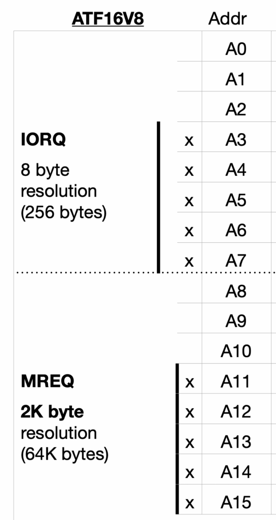
Basically, this fulfills the vast majority of our needs in experimenting with 8-bit devices, as was my goal.
2K resolution address map limitation
However, recently, it was brought to my attention that some well known retro systems, which somebody might want to re-create, wouldn’t fit into this 2K resolution address map limitation.
This then took me back to my original decision to focus solely on the ATF16V8 for all of my MECB platform needs.
In retrospect, I might have been a bit too aggressive in my “Minimalist” guided thinking.
On revisiting this decision, it occurred to me that there was no reason to standardise on only an ATF16V8 solution.
It certainly might have made more sense at the time. But, now that I’m further down the track, with a number of MECB Card’s implemented, it actually makes sense to take a re-look at the 16V8’s bigger brother, the ATF22V10.
Alternative ATF22V10 glue logic solution
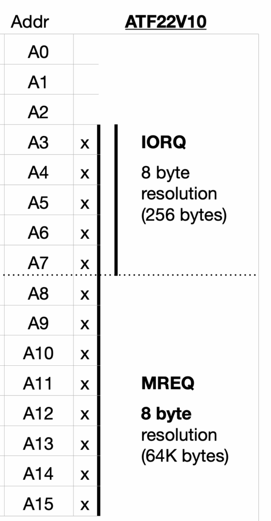
Where the ATF16V8 only allowed me to connect 10 address lines, the ATF22V10 provides 4 extra pins available for me to utilise.
This allows me to fill the missing address lines gap between the 5 high address lines, that I selected for the 2K resolution MREQ addressing, and the 5 lower address lines that provide the 8 byte resolution of the IORQ space.
With the 3 middle address line gap filled, we can now use MREQ based addressing to also define an address block with an 8 byte resolution anywhere within the 64K address space.
The 4th extra pin available on the ATF22V10 is then used to add a 4th Chip Select output, enabling a 4 device peripheral card.
Here’s a combined graphic, I’ve created, to help visualise the difference:
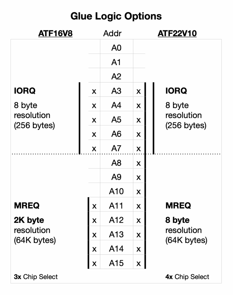
So, by using a ATF22V10, we now have the full A3 – A15 address lines available for defining the address selection glue logic.
Real world example – AIM-65
Using a real world example, this then allows us to re-create the address map of the AIM-65 computer system, which is the real world example that brought this addressing deficiency to my attention.
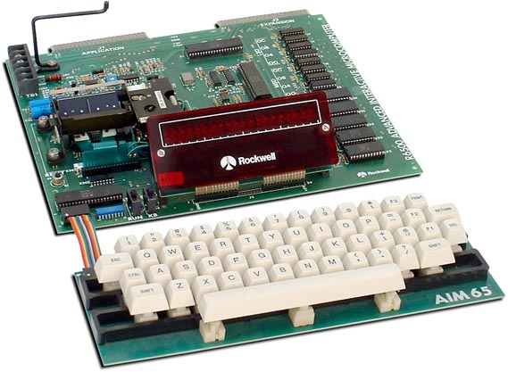
The AIM-65 has a 4K system I/O space at $A000 – $AFFF, divided into 4x 1K device spaces. One of these devices is the 6532 RIOT chip, which includes 128 bytes of RAM.
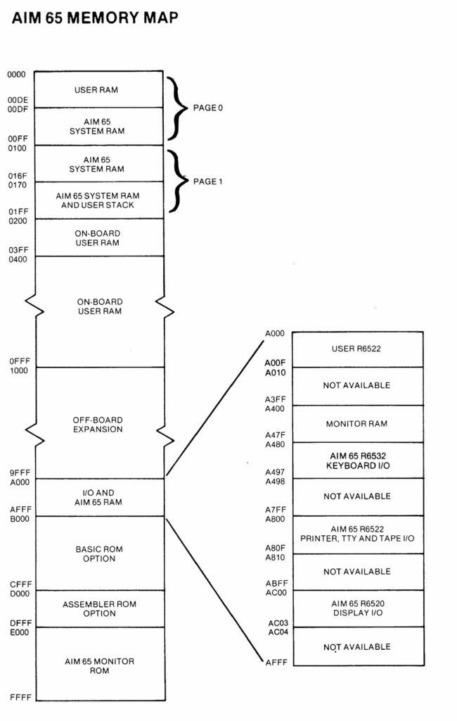
So, with our existing 16V8 PLD limitations, the MREQ 2K bank addressing resolution is not granular enough for the required 1K device address space allocation. Even putting a 6532 RIOT chip in our 256 byte IORQ space, would use up half the IO space with its 128 bytes of onboard RAM.
Using a ATF22V10, instead of the original ATF16V8, resolves this limitation. Enabling a memory map accurate re-creation of an AIM-65 system.
Establishing an expanded MECB glue logic standard
So, to establish standard MECB support for the more capable ATF2V10 PLD, I’ve now done a few things.
Firstly, I’ve created a second KiCAD Template which features a standard PCB routed ATF22V10 PLD. This joins the existing KiCAD Template that features an ATF16V8 PLD.
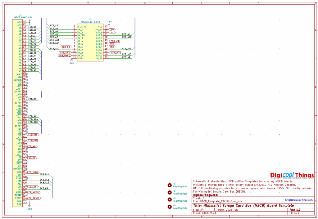
This enables the easy creation of a standard MECB Card using an ATF22V10, instead of an ATF16V8.
Here is what the original ATF16V8 Templates looks like. As you can see both have the PLD placed in a ZIF socket friendly spacing from the DIN bus connector.
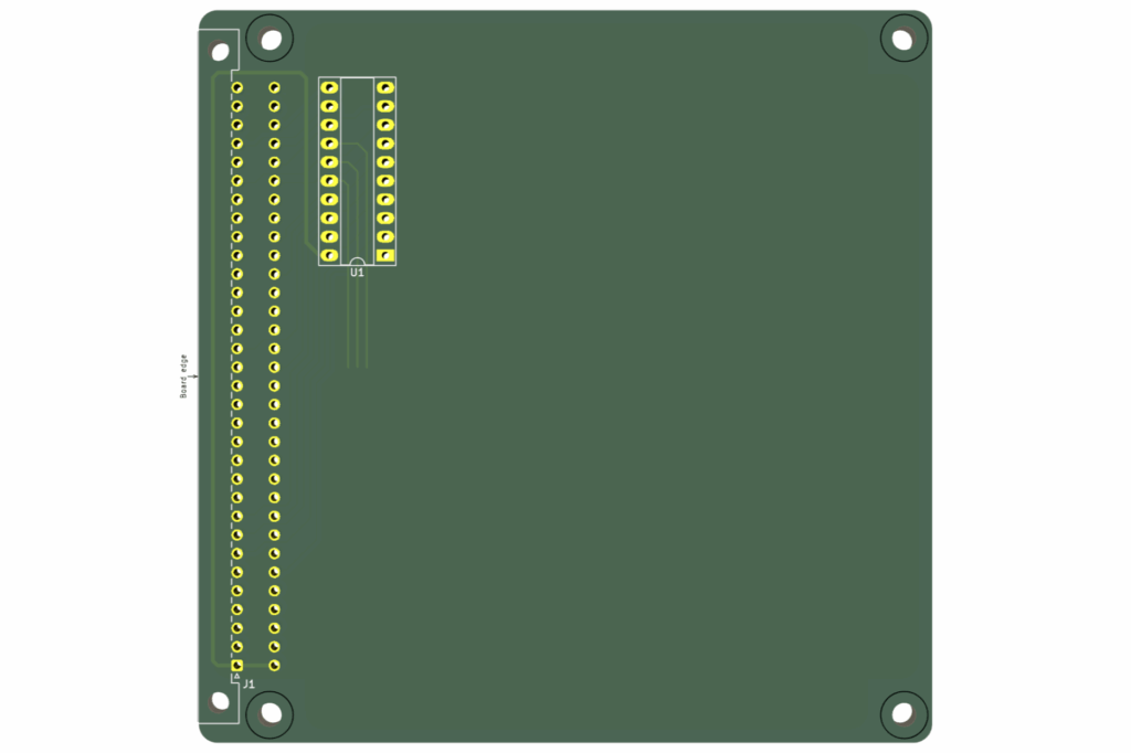
The difference being that one has the original 20-pin ATF16V8 implemented, and the other (new one) has the slightly larger 24-pin ATF22V10 implemented.
You can find both KiCAD Templates in the MECB github repository.
New MECB Prototype 22V10 Card
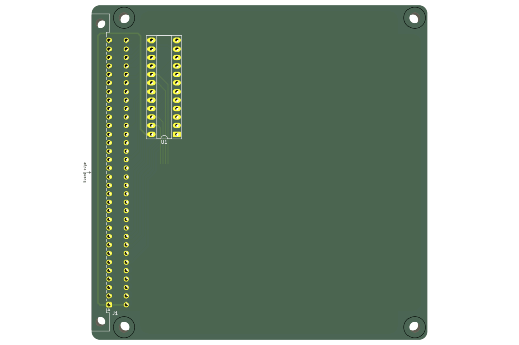
Secondly, I’ve introduced a new MECB Prototype PLD Card based on the ATF22V10.
So, we now have the existing Prototype PLD 16V8 Card, and now a new Prototype PLD 22V10 Card.
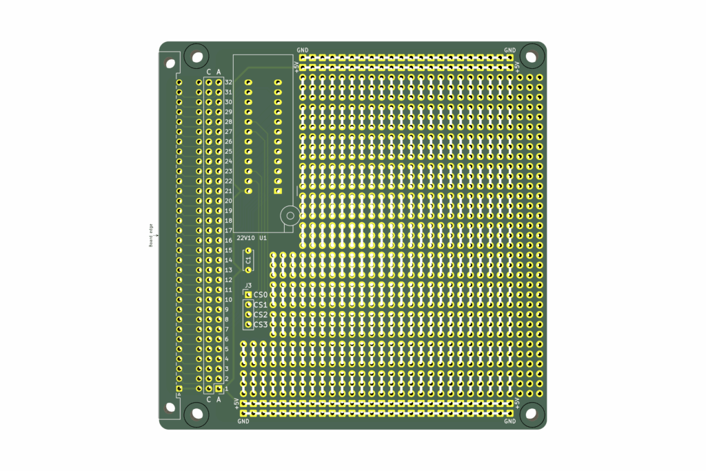
Here’s what the new Prototype ATF22V10 PCB 3D renders looks like:
Both the original Prototype 16V8 and the new Prototype 22V10 Cards are now available on my Tindie Store.
Which PLD you choose for a new MECB card design, is pretty much determined by your project needs.
The existing ATF16V8 has the advantage of reduced cost, and uses the more common 20-pin IC Socket, that most enthusiasts probably already have in their parts drawers.
So, if making a Card that is fine with the 2K MREQ / 8 byte IORQ address bank resolution, then you can just go with the existing ATF16V8 based glue logic solution.
But, if you’re in need of a smaller than 2K memory space allocation for a device, or you want 4 device chip selects on your card, then the ATF22V10 is the way to go.
So, to finish off this video, I’ll assemble a new Prototype 22V10 Card, and demo it’s use with a simple 6821 PIA example (and also with a 6532 RIOT chip, as used in our AIM-65 example).
Below, you can see all the pack components to complete the assembly, including a 24-pin Narrow ZIF socket, to facilitate easily swapping out the ATF22V10 PLD for different prototype project memory space allocations.
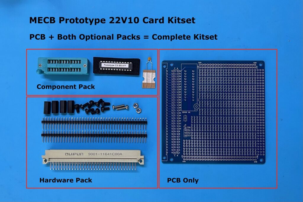
For the Tindie Store, I’ll offer the PLD pre-programmed with a simple $E0-$FF I/O space allocation for four 8 byte device chip selects.

As per the existing Prototype PLD Card, I’ll also include the laminated full colour MECB pin-out guide, if you order both Optional Packs (to make a Complete Kitset).
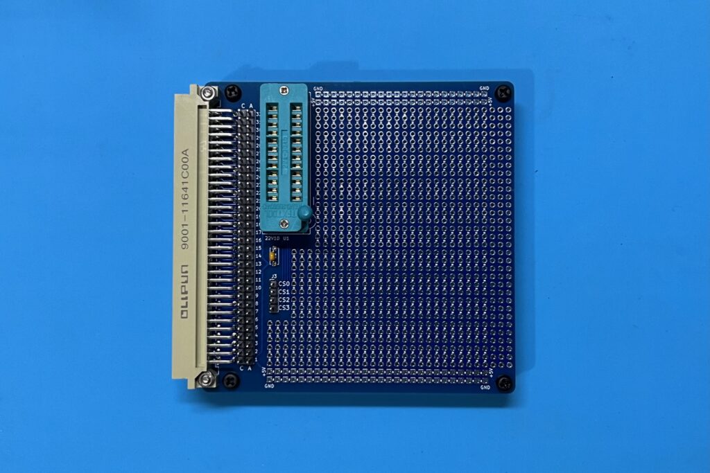
So, let’s get the first Prototype 22V10 Card assembled.
And, here is the assembled Prototype 22V10 Card:
Next, I install the ATF22V10 programmed with my standard $E0 – $FF I/O address range.
6821 PIA based Prototype Card test
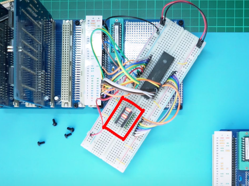
Now, I’ve got a breadboard that’s already populated with a 6821 PIA. To which I’ve just connected PIA Port A to one of my handy 8-bit LED Things.
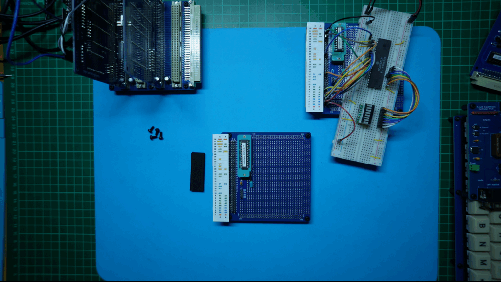
So I just need to hook-up the breadboard to the relevant bus data, address and control lines on my new Prototype 22V10 Card, to allow addressing it with my 6809 CPU card.
In addition I’ll connect Chip Select zero (CS0) to the PIA’s Chip Select. So, with our standard ATF22V10 installed, it will be addressed at IORQ port $E0.
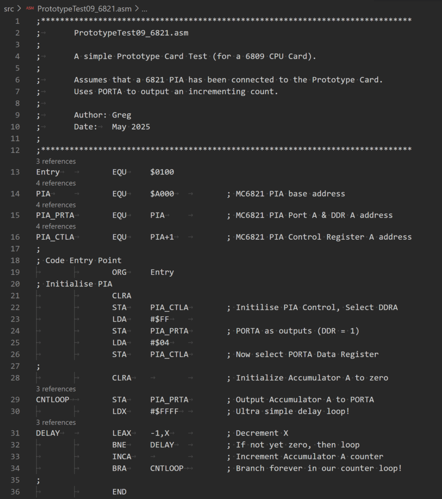
Next I’ve got the same short 6809 Assembly code test program, that I used to test the original ATF16V8 prototype card.
It simply initialises the PIA, with the Port A pins set as outputs, then sends an incrementing byte count to the Port A pins.
Here’s a view of the source code (source available on the MECB github repository):
So, I Assemble that and transfer it over to my MECB 6809 CPU Card, and run it.
And, we have our 8-bit LED Thing showing a counting 8-bit number.
This successfully confirms our glue-logic ATF22V10 is correctly decoding the $E0 I/O port Chip Select zero (CS0).
AIM-65 System I/O decode test example
To show how the new ATF22V10 glue logic PLD can now be used to replicate the earlier mentioned AIM-65 system I/O of 4 devices allocated 1K of address space each, within the address range of $A000 – $AFFF, I next update the PLD to reflect this.
Below is the PLD source for recreating the AIM-65 system I/O space.

As you can see I have configured the four Chip Select outputs (CS0 – CS3), to provide 1K each in the address range $A000 – $AFFF.
So, I next re-program the ATF22V10 with this new code and re-insert the ATF22V10 into the Prototype Card.
Now, to go along with that, I also have to update the CPU Card’s PLD to exclude the $A000 – $AFFF address range from the CPU Card’s onboard RAM allocation, to avoid any address conflict.
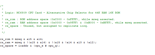
Below is the CPU Cards PLD source, which takes the standard 48K RAM / 16K ROM memory map, and excludes the $A000 – $AFFF block to make a 44K RAM allocation with 40K RAM from $0000 – $9FFF, and additional 4K from $B000 – $BFFF, with the top 16K of memory allocated to ROM.
So, I next re-program the CPU Card’s PLD, and re-insert it into the CPU Card.
With this done, I first verify all is still operating as expected, by updating the existing 6821 PIA test program, to instead address the PIA at $A000, instead of it’s previous $E0 I/O address.
A quick re-test with this updated code confirms we are decoding the memory map, as expected.
6532 RIOT based Prototype Card test
So, next, I wire-up a 6532 RIOT chip, in place of the 6821 PIA. The 6532 uses the same bus signals as the 6821, just with the addition of some extra address lines for the on-chip 128 bytes of RAM.
I also connect the 6532 to Chip Select 1 (CS1) of our Prototype 22V10 Card, just for fun, as it replicates the AIM 65 addressing of $A400 – $A7FF.
With the 6532 RIOT chip now in place of the 6821 PIA, I just need to make a new variation of the test Assembly code, so it now initialises and addresses the 6532 Port for the LED counting.
Below is the resulting 6809 Assembly code. As, you see, it’s pretty similar to the earlier 6821 version.
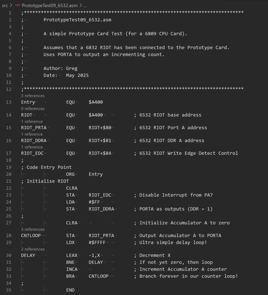
You can see, from the listing’s Entry EQU, that I’m going to test the 6532’s internal RAM by simply Assembling our test program to load and run at address $A400.
So, we’re essentially transferring the test program into the 6532’s internal 128 byte RAM space, and running it from there. Which seems like a good initial 6532 RAM test!
Finally, I get that Assembled and transferred to the CPU Card. Note that the transfer itself would fail, if there is no RAM present at the $A400 load address.
With, that New code Assembled and loaded to the CPU Card, I just need to execute G A400 (in my ASSIT09 monitor).
And, once again, we have success!
As usual, I’ve uploaded both the 6821 and the 6532 test code to the MECB github repository, under the new Prototype 22V10 folder, if you want to replicate my tests.
Have fun.