The Backplane was the first Minimalist Europe Card Bus PCB that I designed. Which does obviously make sense, as a Backplane is needed before we can connect other MECB Cards together!
It has served me well, but recently one of the newer members of the Forum (Michael), offered some really useful “new user perspective” feedback.
These useful updates resolve a couple of potential gotchas!
Join me as I present and explain the v1.2 Backplane updates, and build & test the first v1.2 Backplane.
Firstly, Michael noted that the silkscreen could do with some updates to further clarify the Electrolytic Capacitor orientation.
There was also discussion that it would be useful to have a LED power indicator.
Sometimes you are just too close to something to notice the obvious. I’ve certainly been caught more than once, thinking that I had a fault, when everything was dead following switch-on! Only to then realise that I’d disconnected my USB power plug, and forgot to plug it back in!
Obviously, in this case, a power LED would have clearly indicated if power was actually On, or not.
So, our updated Backplane now has more clearly defined Capacitor footprint silkscreens, and we now have a Power LED, positioned next to the power switch.
This means that the optional Components pack on my Tindie Store now also includes a LED and a Resistor.
Finally, Michael pointed out that the USB-C Power Socket module, does not work with smart USB-C power sources.
I hadn’t noticed this myself, as I have been using Raspberry Pi USB-C Power Adapters for my USB-C Powered projects.
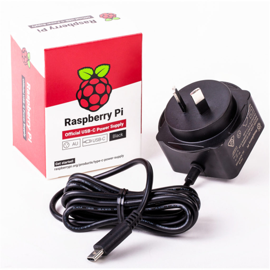
The Raspberry Pi Power Adapters (I believe), are just dumb Power Adapters, terminated with a modern USB-C plug instead of the traditional DC plug. I’ve found them very useful, and economical, for powering my 5V projects.
But recently, I also got myself a really nice 300W PD3.1 capable USB supply for my workbench. It features a total of 8 USB power outputs, and is also capable of supplying 28V at 5A.
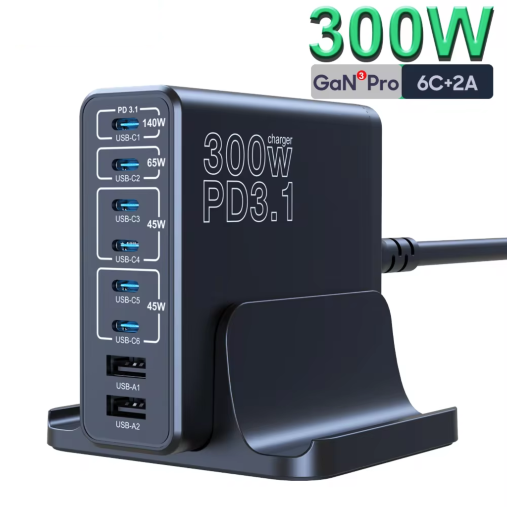
This USB Supply is perfect for my new MINIWARE MHP50 Mini Hot Plate Pre-heater, which draws quite a bit of power, but also can be powered from a PD3.0 or PD3.1 capable USB-C Power Supply.

I expect that a lot more of our new devices in the future will be USB-C powered, using smart Power Delivery negotiation.
So, to resolve this for our USB-C powered retro Backplane, I hunted down some suitably compact, smart Power Deliver compliant USB-C modules.
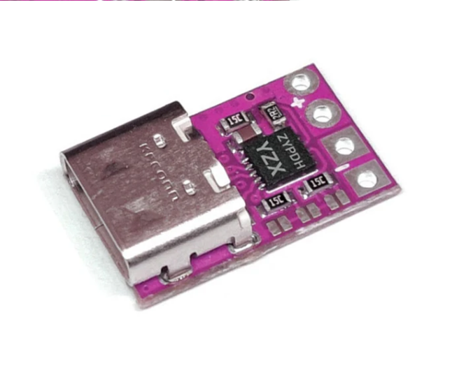
These PD Compliant USB-C Modules still work with dumb 5V USB-C Power Sources (like the Raspberry Pi plug packs), but are also capable of properly negotiating and delivering different voltages when connected to a smart PD compliant USB-C Power Source.
As these modules are capable of negotiating different voltages, I will ensure that the modules I supply come pre-configured for 5V delivery. To avoid any accidents!
These smart USB-C modules are a bit more expensive than the dumb USB-C socket modules, and you only actually need one if you intend using a smart USB-C Power Supply.
Therefore, I’ve decided to add them as an additional option to my Tindie Store MECB Backplane listing.
If you just order the Components Pack, it will default to including the dumb USB-C Power Socket module (as before), but I’ve now added an additional “upgrade” option which swaps-out the dumb USB-C module in the Component Pack, for one of the new smart PD3.0 compliant USB-C modules.
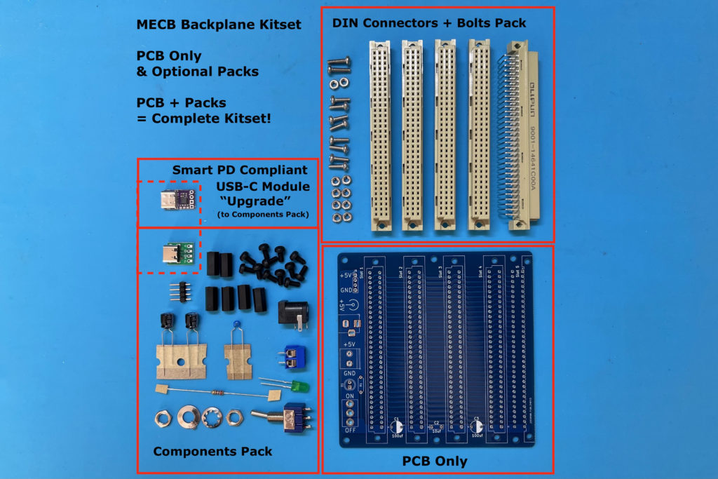
Hopefully this lets everyone choose to get only what they actually need.
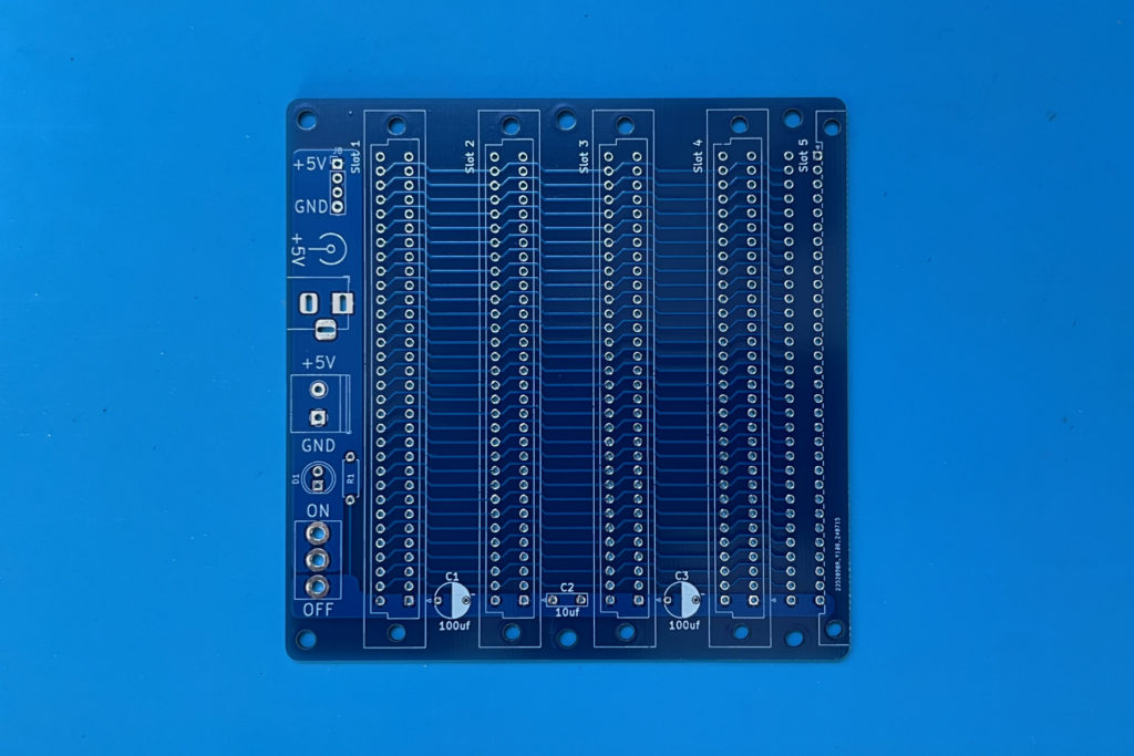
So, here is a new Backplane v1.2 PCB, where you can see the new space for the Power LED and also the updated silkscreen Capacitor footprints.
The new PD compliant USB-C Power Modules are configurable, via solder pad jumpers, to supply either 5V, 9V, 12V, 15V, or 20V.
By default (as I receive them), they negotiate 20V power output from a PD compliant USB-C Power Supply.
By soldering two jumper pads they are reconfigured for 5V. As I said above, I’m going to pre-configure the solder jumpers for 5V power, and test them, before I give them to anybody.
I’d hate to think that somebody might otherwise feed 20V into their MECB Backplane!
In the video linked above, I demonstrate connecting my usual Raspberry Pi plug-pack, and we see that I still measure the expected 5V power output.
However, we also see that with my smart USB Power supply connected to the existing dumb USB-C Power module, there is no output (i.e. zero volts!), as Michael reported.
But, when I swap the smart USB Power Source to the new smart Power Delivery module, we see that a new module (by default), negotiates a 20V supply. So, we have power, but not what we want for our retro 5V Backplane!
I then solder bridge a couple of the voltage selection jumpers, and when I try again, I finally get the desired 5V.
With that demonstrated, I then proceed with a new Backplane assembly.
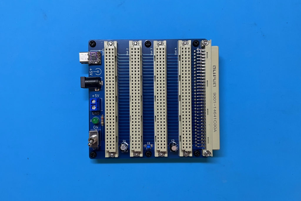
Here’s what the updated v1.2 Backplane looks like assembled, with one of my new Power Delivery compliant USB-C modules fitted:
Next, I apply power using my USB Power Delivery compliant power source, and I check that we have 5V on the power line, and also observe the new Power LED in action.
After this, I insert my current MECB system cards, to replace my existing Backplane.
Then, after applying power again, we’re up and running with my usual power-up ASSIST09 monitor prompt.
Finally, I also demonstrate on the video that the new PD Compliant USB-C Power Module still works with my dumb Raspberry Pi USB-C power adapter.
All good!
So, there we have it, some small (but very useful), upgrades to the standard MECB Backplane offering!
