
This follows on from my Introduction of the Minimalist Europe Card Bus (MECB), where I outlined my preferred design, for recreating some of my 8-bit CPU experiences from the late 1970’s and early 1980’s.
For this modular Bus based system, the first thing we’ll need is a Backplane for connecting our modular boards together.
Join me, as I first walk-through the design of my MECB Backplane, and I then assemble my first Backplane. The Backplane will then be ready to accept whichever modular MECB boards, that I’d like to assemble together to create a system.
Background
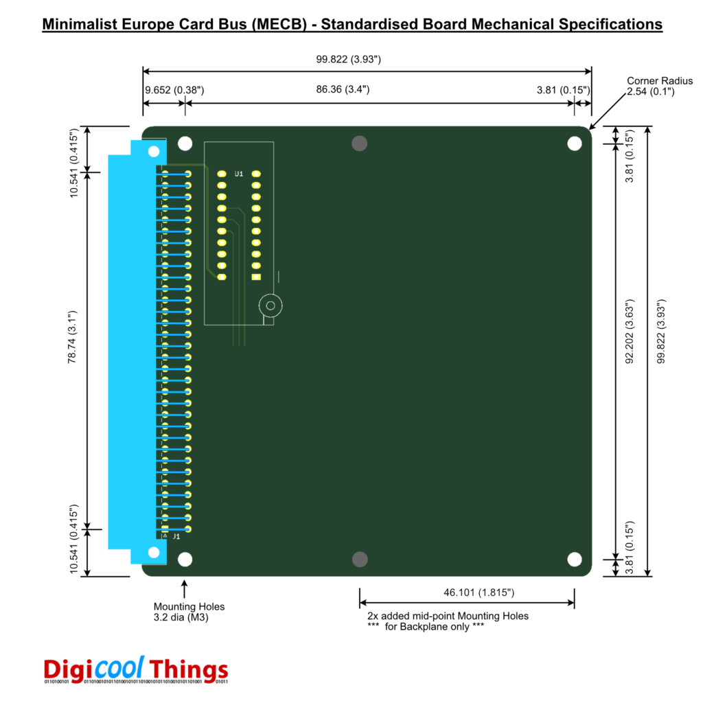
In my Minimalist Europe Card Bus (MECB) – Background & Introduction video, I came to the conclusion that I would first develop a standardised Mechanical Specification for a Minimalist ECB (MECB) board.
This was completed, providing the basis for my first MECB board design to get underway, whilst ensuring that all MECB boards that I develop will be consistent, for a tidy and attractive system solution.
Design
So, based on the MECB’s just under 100mm square board size, let’s take a look at our preferred Backplane design parameters .
Backplane Design Parameters:
- 4x 64-pin (Row A&C) DIN 41612 type C straight female backplane connectors, centred across the board width.
- A 5th Right Angle female DIN connector, to facilitate mounting a board horizontally for ease of access during hardware or software debugging and also for prototype board development etc. In addition, the horizontal connector could also allow for a future Backplane extension board.
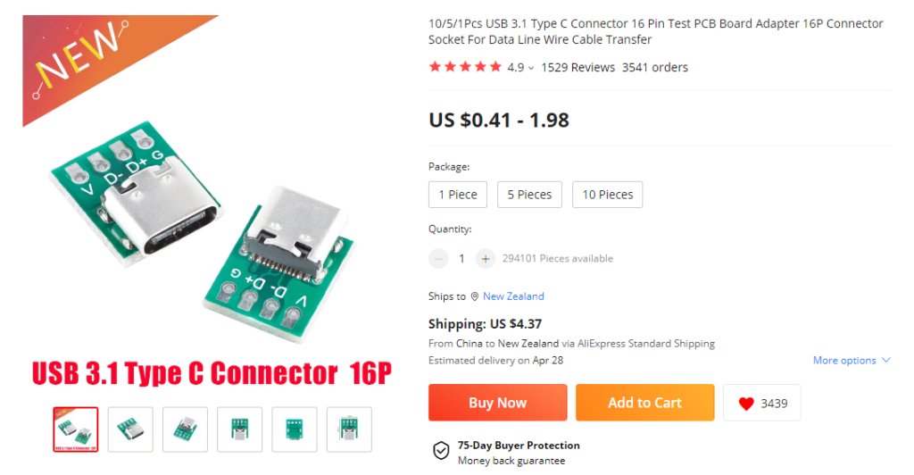
- Multiple 5V power connector options, including a DC Power Connector, a modern USB-C Power Connector, and a Screw Terminal connector to support any other desired power source.
- A Power Switch to allow switching on/off the power to the backplane connectors.
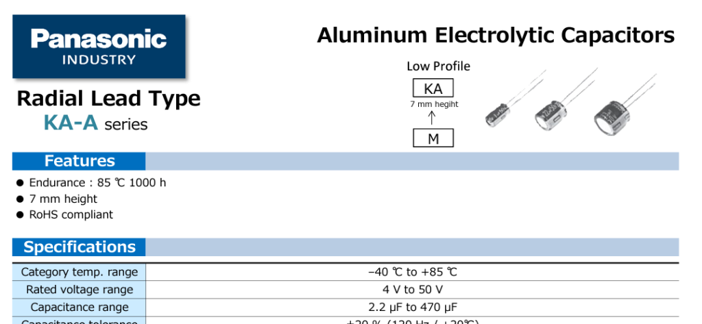
- Some Backplane bypass / smoothing capacitors, perhaps 100uf & 10uf would be appropriate, leaving the smaller 0.1uf typical bypass values to be located close to the IC’s on each MECB modular board.
- Use only through-hole components, in keeping with the early 8-bit retro MECB theme.
Backplane Design Notes:
- 6x M3 mounting holes are provided for mechanical support (as per the standardised Mechanical Specification).
- A USB-C receptacle module, which mounts with pin headers, is used to facilitate through-hole components only.
- Low profile 100uf capacitors are desired for a clean and tidy finish.
The USB-C receptacle module was obtained from AliExpress:
Some nice & tidy Panasonic Low Profile Electrolytic capacitors were located from Mouser Electronics:
Schematic
As expected, a Backplane design makes for a relatively simple schematic. This has been completed in KiCAD, based on the standardised Mechanical Specification KiCAD Template, that I earlier created.

PCB Layout
After some tweaking, I finalised the PCB layout ready for ordering from JLCPCB, as revision 1.1

Assembly
You can view my linked Youtube video for the full Assembly walk-through.
With assembly completed, we now have our first assembled MECB Backplane, ready to accept some MECB boards:

Links
MECB on GitHub – Board Mechanical Specification / KiCAD Template
So, let’s say I want to redesign a backplane that conforms to this design standard, but instead has 5-6 connectors in a shorter profile on both the top, and flipped over underneath as well, so when stood on its edge, would look something like this:
|
X|
|X
X|
|X
X|
rather than your current design of:
|
|X
|
|X
|
|X
|
|X
|
|X
would this break your standard? I have another question after you help me with this one…
That should work. The board size would differ from my “keep it simple” single standard of 100mm square PCB size.
But, clearly this is a special requirement in order to create a low-profile system.
With this in mind, I guess whether you have 5 or 6 connectors (or even just 4) on a “back-to-back” backplane, would depend on your maximum low-profile system height that you are wanting to achieve.
This might also mean that, as well as a shorter backplane PCB, it might also be wider if you were also needing to move the power connection / filter capacitors to sit alongside (at the ends of) the row the connectors.
The existing standard board mechanical design (and the Cards already designed) include M3 mounting holes in each corner, so if the connnectors were spaced appropriately then standard size PCB Spacers could be used to support the horizontal mounting of Cards in your low-profile double-sided backplane.
Well, my thought would be to keep it within the 100mm wide standard, but as you say, condensed by double-siding the connectors, one side upside-down to keep pinouts aligned, but then one row would then be used for a “bus connecting” card that would have a secondary connector allowing a ribbon connection to another condensed bus pcb right beside the first one – that way all the standard 100mm x 100mm cpu, I/O, video, peripheral cards would all still be accommodated with cnc routed aluminium endplates to keep the bugs out of the case for those cards with ports and interfaces requiring external access.
So, yes, my next question was, I have a stack of 100 pin molex interfaces and matching ribbon cables recovered from a stack of old 2900 series cisco routers, interface detailed here: https://tools.molex.com/pdm_docs/sd/015922030_sd.pdf – so how would a dual bus connected via such a ribbon cable fare as far as noise, crosstalk and attenuation is concerned? The ribbon cables themselves are no longer than 200mm, but a rough measure and test with my imagination swapped in for my cards/bus shows it should be just enough to allow two of my proposed low profile cards to be mounted side-by-side and connected via this ribbon. I have some spares of these recovered interfaces and ribbon cables, so might have to learn how to use kicad and try my hand at pcb design if you’re up for some guidance under my pestering? If it won’t work, or it’s too hard, then I’m sure one low profile bus card would still do the trick… but where’s the challenge in that??
I’d suspect that connecting 2 backplanes together with a 200mm ribbon cable might be problematic?
Firstly, I’d suggest you’d want every alternate wire of a flat ribbon to be GND, to provide some signal separation / shielding. With a 100 wire cable this would only allow 50 connections, although this may still be sufficient for the bus signals we are using.
But, I imagine a cable connecting 2 backplanes would probably create multiple signal reflection points with the impedance changes at each connection point, likely requiring some bus termination.
However, the existing Minimalist ECB small board design was intended for small system experimentation, as such, board space was also saved on the short 100mm square boards by not including bus drivers that would normally be used on a bigger system. To drive a terminated bus, drivers would no doubt be required.
Of course, you never really know until you prototype such a system and monitor the resulting signals.
I suppose the ultimate consideration is whether you really need a low-profile system? Considering that many early computers (in cases with keyboard), had a higher back half of the case, to accomodate expansion card height.
Well, probably just stick to a single condensed double-sided bus then, I think… I’d much rather the simplicity of what you’ve designed and achieved here, so even a single low-profile bus would work just fine with the various cpu, I/O, video cards you’re designing and building here. I wouldn’t have the nous required to ferret out my own designs, and boring/lonely even if I had, so I have to build it to someone else’s standard anyway. My low profile idea would be intended to work exactly as your bus does already, but in a form factor I can hide in a case of my own design. The flexibility and modularity of your setup is an excellent base for a particularly hackable and flexible 8-bit hobbyist system… 🙂
Yes, you’ve had me putting quite a bit of thought into how I could achieve a low profile backplane solution that you were keen on, but I haven’t really come up with anything as yet.
Also, the upside-down Cards (on one side), due to reversed connectors on the back of a backplane PCB is also not really ideal.
I did start thinking down the track of 2 right-angle “opposing edge” located connectors, for a flat stackable “sandwich” backplane board design, but this would have the issue of needing enough PCB space to “via swap” all of the signals over, for opposing board edge “upright” right-angle connectors.
Perhaps achievable with the standard 100mm square board size. But, for now, I should probably get back to focussing on my next card design. LOL
Ooh! I like your idea! I’d settle for something like that if it could be made to work – I imagine at least 4 useable backplane connectors across the two interconnected boards (not including interconnects themselves) could be enough, tho one with an extra bus connector to make 5 for a little extra height might be handy enough to wear the height penalty – but yes, you concentrate on your next video, I’ll carry on dreaming up more ideas for now…