This Part 4 of my CreatiVision series is the culmination of my RetroChallenge 2024/10 project, where I designed my CreatiVision Mechanical Keyboard, to complete my CreatiVision project series.
The progress and milestones of my CreatiVision Keyboard creation have already been documented, via my regular update posts on my RetroChallenge 2024 blog.
Join me as I assemble my first Keyboard, run it through its first tests, and fix a coding oversight.
We’re also effectively celebrating the completion of my overall CreatiVision re-Creation project, which started with Part 1 of this series.
As a reminder, I started off (in Part 1) by configuring my MECB based system to successfully re-create the CreatiVision hardware, which allowed me to then run CreatiVision software (unchanged), but I was still in need of a controller interface.
In Part 2, I then designed my CreatiVision Controller interface, which also doubled as a controller upgrade for an original CreatiVision console, providing for two Atari style joysticks and a PS/2 keyboard interface.
In Part 3, I did a major version upgrade to my Controller interface, bringing it now to the final v2.0. It now also supports the new Atari CX78+ dual-button joysticks (a perfect match for the CreatiVision), as well as auto-detection of the attached joystick type, and a much better power supply arangement when connecting to an original CreatiVision console.
Now, in this Part 4, I complete my CreatiVision project journey, with a custom designed, and true to the original layout & key legends, CreatiVision Mechanical Keyboard.
So, in preparation for final testing of my first completed Keyboard, I’ve laid out on my workbench all of the components necessary for assembling a CreatiVision Keyboard.
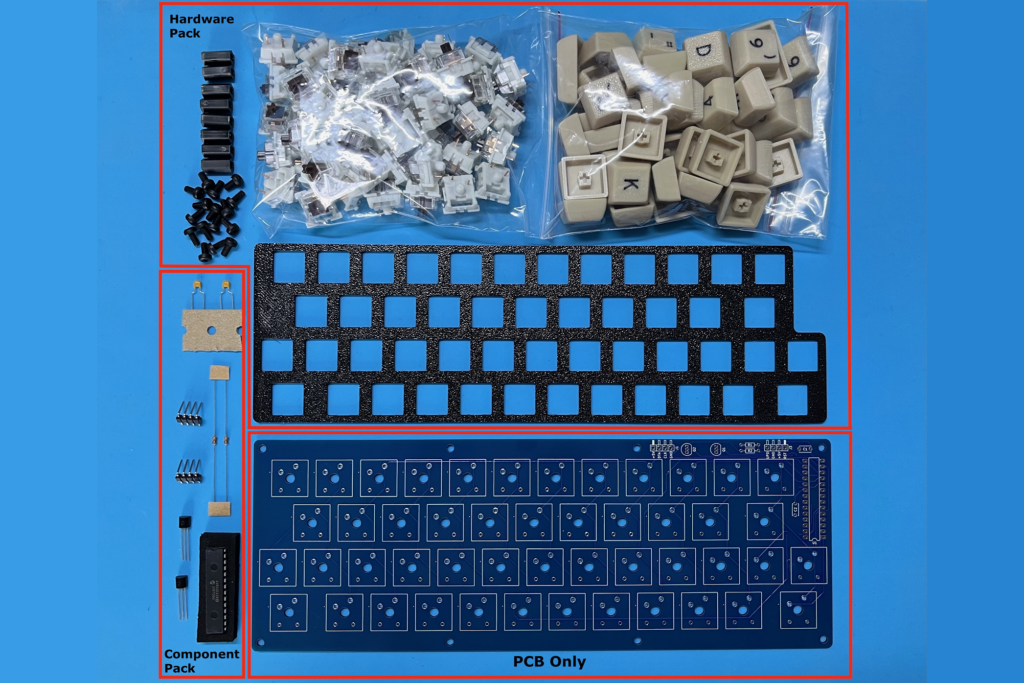
To start with, I assemble the electronic components onto the keyboard PCB.
A couple of points here.
Firstly, I’m not using an IC socket for the SDIP 28-pin AVR microcontroller, as I want the IC to be as low-profile on the PCB as possible.
Secondly, the two TO-92 packaged MOSFETs are mounted lying flat, with the leads bent at 90 degrees, for the same reason. To be as low-profile on the PCB as possible.
Likewise, I have specified right-angle headers for the UPDI programmer connection and for the PS/2 interface connection, to keep them low-profile as well.
If you choose to, the headers could instead be mounted on the back of the PCB, if this would result in easier connections.
What you actually choose to do may be decided by how you intend to mount your keyboard.
So, let’s get the components mounted on the PCB, and have a look at the finished result.
And here is the result. Note how I’ve chosen to mount the different components.
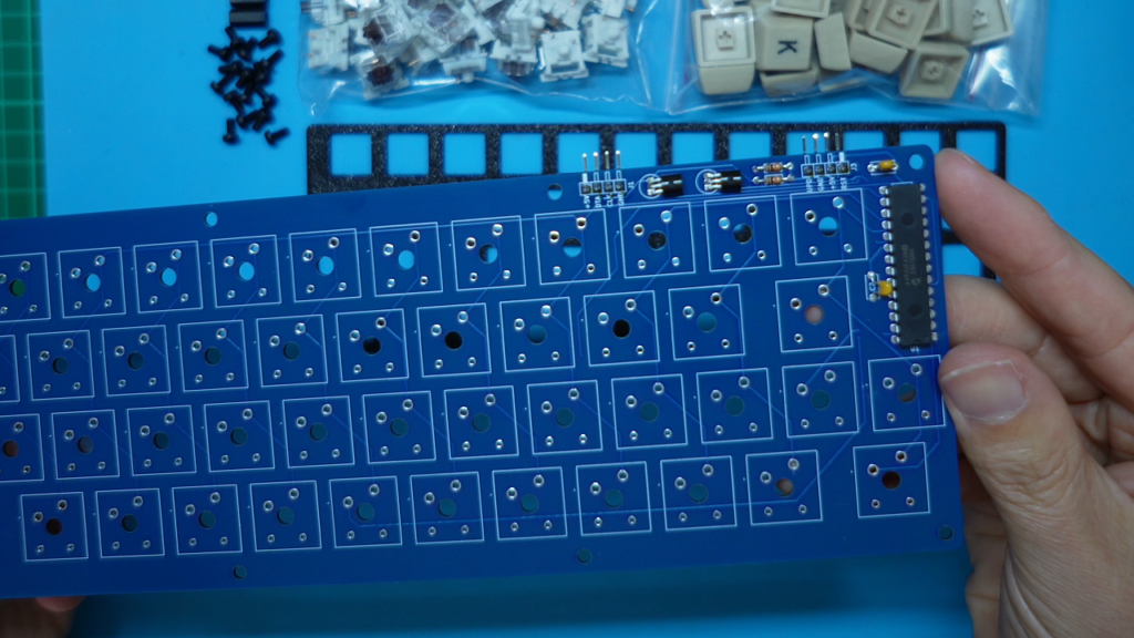
I actually chose to mount the two right-angle headers on the back of the PCB.
Now, before proceeding further I connect my PICkit5 programmer to the UPDI header connection, and program the AVR microcontroller.
Now, if you obtained a kitset from my Tindie Store, the AVR microcontroller is already programmed, so you won’t need to take this step yourself.
Okay, the next step is to mount the 48 key switches on the keyboard plate. Each switch just snaps into place.
While doing this, I also ensure that all of the key switch pins are nice and straight. Any bent pins are carefully straightened.
Okay, with all the key switches mounted on the keyboard plate, and the pins all confirmed as straight, the PCB should just drop into place.
With the PCB dropped into place, I now go ahead with soldering all the switches to the PCB.
Next, I screw in the eight PCB stand-offs, so that my keyboard sits nicely on my desktop.
All that’s left now, is to pop-on the key-caps to complete our CreatiVision Keyboard, replicating the layout of the original CreatiVision moving key keyboard accessory.
With that done, our keyboard is now fully assembled, and ready to go.
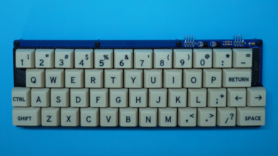
With the keyboard assembled, I could connect up a PS/2 keyboard cable. But for my purposes, I’m going to just use some hook-up leads, to connect the Keyboard’s PS/2 connection header directly to the PS/2 header on our CreatiVision Controller PCB.
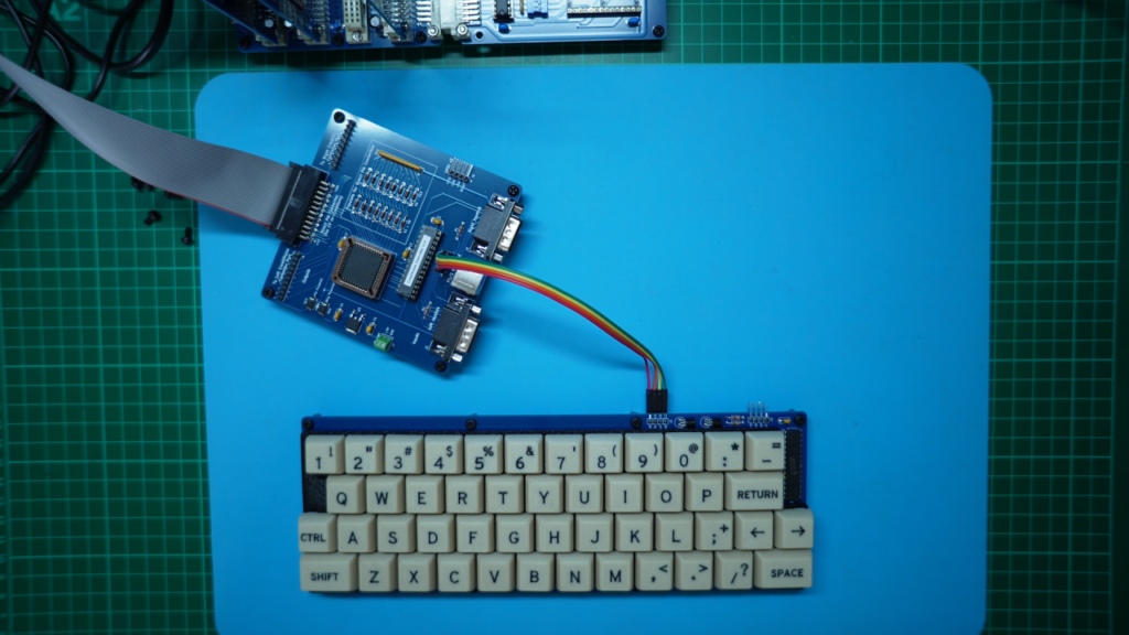
Now, we are ready to give the completed keyboard, it’s first test.
So, next, I turn-on my CreatiVision re-Creation, which currently has the controller “Diagnostic B” ROM image selected.
Time to give the keyboard a try.
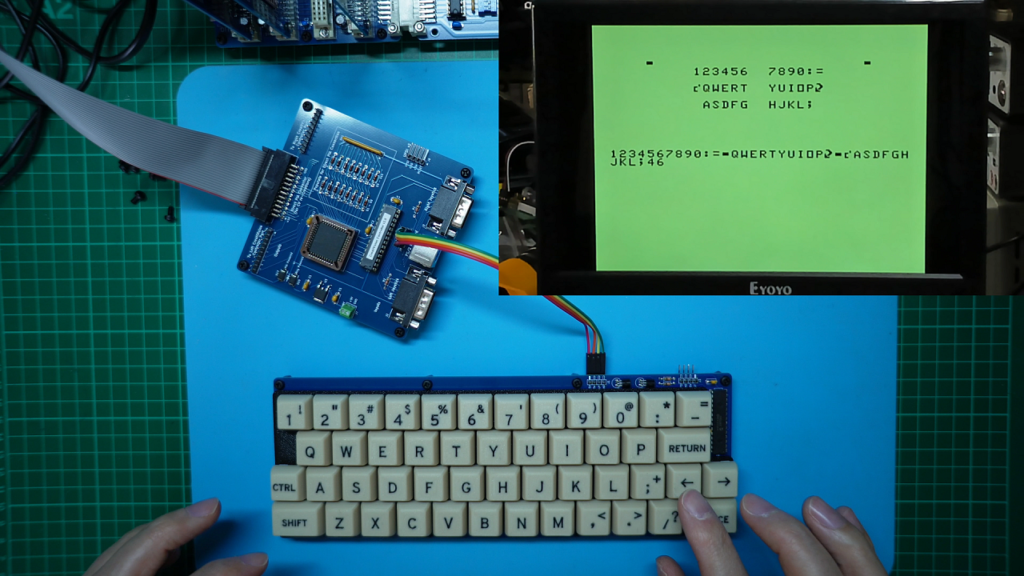
It’s working great!
This keyboard is much better than using the original controllers as a keyboard, and also much better than using any old PS/2 keyboard, as we now have just the expected 48 keys of the CreatiVision keyboard, with their correct key layout and key legends.
Well, that’s it. I’m now happy to call my CreatiVision re-Creation project, complete.
I’m also happy that this overall project (starting from Part 1), not only resulted in a full hardware replication of a real CreatiVision, it also provided the option of a replacement Controller interface and Keyboard for real CreatiVision consoles.
If you’d like to play with your own CreatiVision system, either as a re-creation, or to supplement an original CreatiVision console with improved controllers and a mechanical keyboard, then be sure to visit my Tindie Store to check-out the kitset options.
