In Part 2, I presented my CreatiVision Controller, which had already gone through three revisions to bring it to v1.2, where I was finally happy to share my journey with others.
Since then, I’ve made some exciting and significant changes to my CreatiVision Controller interface, resulting in a major version increment to v2.0
Join me as I present, and walk-through, the v2.0 changes. Exciting times!
I’m pretty excited about the v2.0 changes, which I believe brings my CreatiVision Controller interface to the next level, and finalises this particular component of my CreatiVision re-Creation project.
I am really proud of the finished result.
The first change is relevant to using the controller with an original CreatiVision Console. The change itself is reasonably trivial, but also relatively significant.
As you’ll probably remember from Part 2, I discovered that when using the Controller with an original CreatiVision Console, it was necessary (for reliable operation), to connect-up a ground reference, so that the two devices had a common ground.
As with my other 5V projects, I utilised a USB-C Module for actually powering the Controller from a separate power supply.
Now, on reflection, it seemed to me to be a bit silly to use a separate Power Supply, when we also needed to connect to the Console’s Ground reference.
Furthermore, when I finally found the CreatiVision’s Cassette Port pinout, I realised that the pin next to the ground pin (which I was using for the Ground reference), was indeed a power pin.
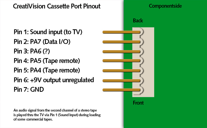
Unfortunately, not the regulated 5V Power that we want, but Power none the less.
As it turns out the Cassette port power pin is the unregulated (approximately 9V), DC input to the onboard 5V regulator.
So, it seemed to make more sense to instead use a 2-core wire to pick-up both the Ground and the 9V supply from the Console’s Cassette port, given that we needed the Ground connection anyway. This then does away with needing a separate power supply.
I’ve therefore replaced the USB-C Power module on the CreatiVision Controller, with a 5V regulator and a new DC Power Input terminal for Ground and 9V DC connection.
This 5V power feed also remains isolated with a schottky diode, so you still have the alternative of the J6 direct PIA Connector 5V power supply pins.
Right, lets talk about the second, and more significant change.
Recently, I got myself a brand new recently re-released Atari CX78+ Joystick Gamepad.
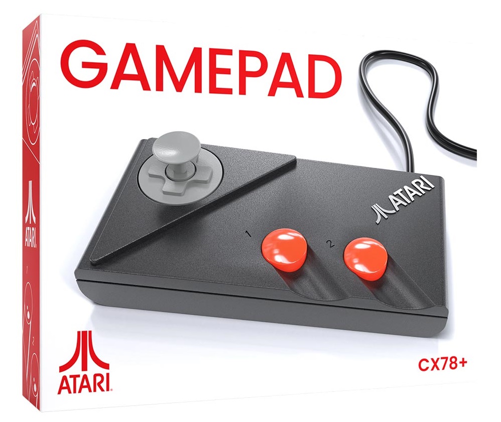
This is a virtually exact recreation of the original Atari 7800 dual-button gamepad controller, from the 1980’s. Re-released as an accessory for the also recently released Atari 2600+ Console, and also the upcoming Atari 7800+ Console.
With one of these controllers in my hand, it occurred to me that this would make a perfect controller for a Creativison Console. Still only 8 directions, but importantly, two buttoned and also currently available to purchase brand new.
Furthermore, Atari has recently announced that this summer (late November), they are releasing a Wireless version, which uses a DB9 wireless dongle. This also allows these wireless Atari two-button Joypad controllers to be used with the original Atari 2600 and the recent 2600+ consoles.
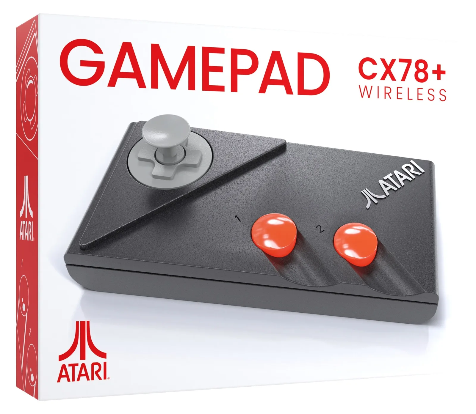
This means, we’ll be able to buy brand new wired and also wireless Atari CX78+ two-button joystick gamepads. Awesome!
One of the good things about the Atari 7800 dual-button controllers is that they were designed so that, by default, either button can replicate an original Atari joystick’s single button.
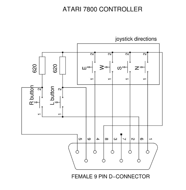
However, if the buttons are read in a special way, you can also detect that it is an Atari 7800 compatible dual-button controller, and then appropriately read the two button values separately.
Now, to do this magic, it is necessary to interface to all 7 joystick control pins. i.e. The 4 direction switches and the single button pin 6, as well as both the additional pins 5 and 9.
Currently, with the existing version 1.2 CreatiVision Controller, I only interfaced to 6 joystick control pins on each joystick.
So, we need 2 more GPIO inputs on our microcontroller, to allow support for autodetecting and using both left & right Atari CX78+ controllers in 2-button mode.
Unfortunately, the 28-pin AVR ‘DA’ microcontroller that I’m currently using, only supports a total of 23 GPIO, including the pin that I’m currently using for the optional hardware reset circuit.
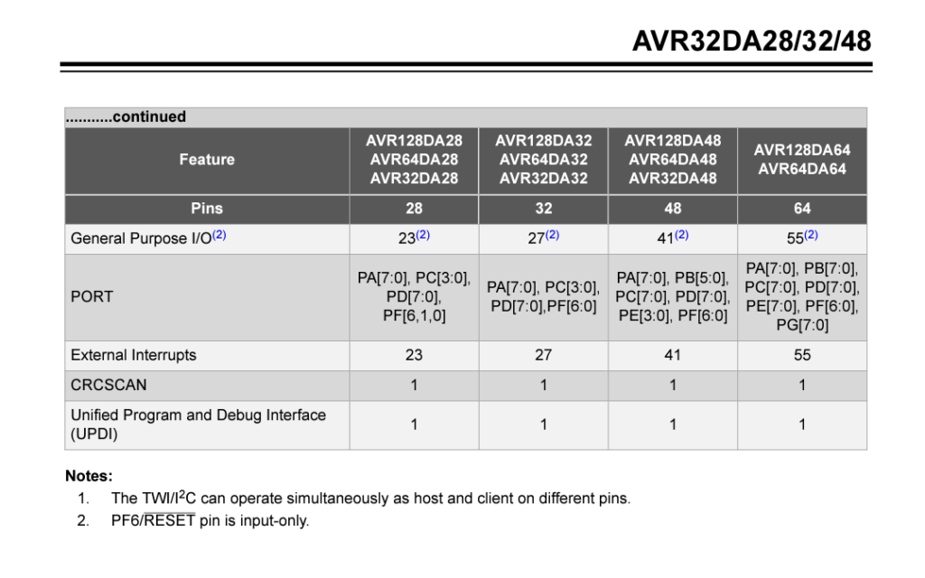
We now need 24 GPIO pins. That is, 8 for the MT8816, 2 for the PS/2 keyboard port, then 7 each for the two joysticks. So, 24 in total. With the existing microcontroller, we are 1 GPIO pin short!
Fortunately, I found that Microchip’s recent AVR ‘EA’ microcontroller family, has the same pin-out as the ‘DA’ series, but now supports 24 GPIO.
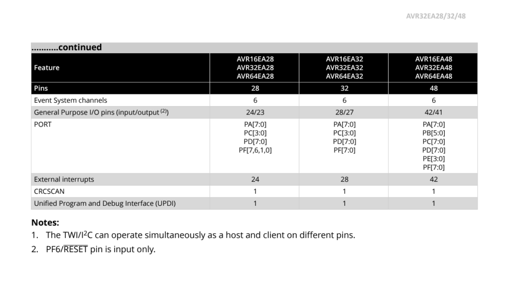
It does this by also allowing the previously dedicated UPDI programming pin, to also be re-defined as an additional GPIO pin.
So, I can re-assign both the Reset and the UPDI pins to the needed 2 extra Joystick GPIO pins, and still use our familiar retro-friendly 28-pin Through-Hole (TH) AVR 8-bit microcontroller.
Great!
But, there is one small issue. In order to program the AVR ‘EA’ family microcontroller, when using the UPDI pin as a GPIO pin, you need a High-Voltage (HV) capable UPDI programmer.
The newer HV component is how the GPIO assigned pin can be overridden to enable its UPDI functionality.
Although my existing MPLAB SNAP programmer does UPDI, it unfortunately doesn’t support HV UPDI.
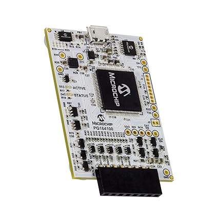
So, it looked like now was the time I should make the jump to the more capable PICkit 5 in-circuit debugger / programmer.
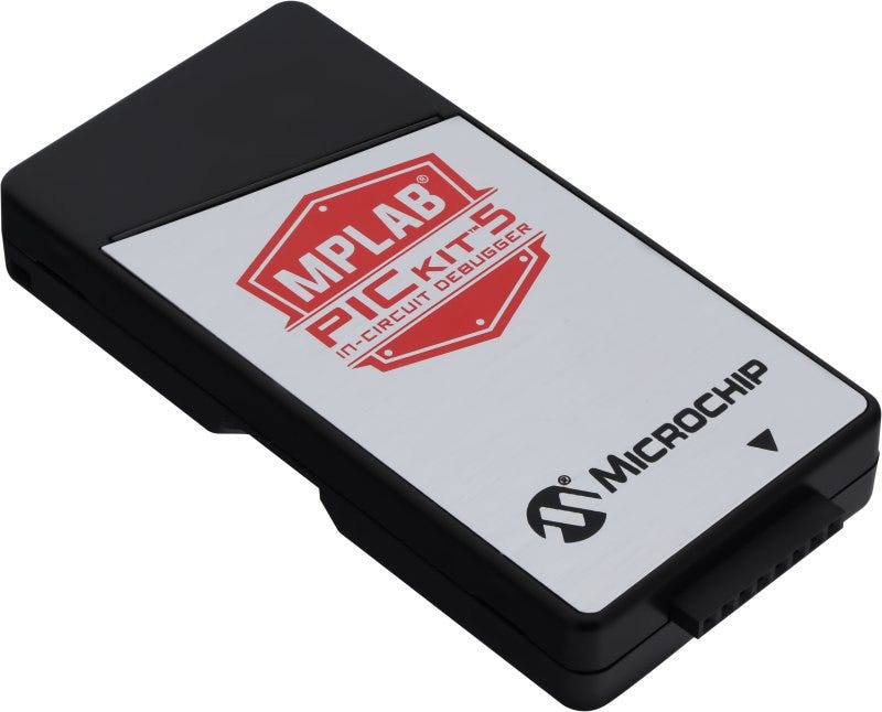
These are more expensive than the hobbyist SNAP device I had been using, but fortunately the PICkit 5 is relatively new and also more affordable than the previous PICKit 4 model was.
So it’s probably a good investment for this, and future projects.
So, with all that explained I now had a workable plan!
First off, was to develop some code to test my ability to detect and interface to the Atari 7800 2 button joysticks.
So, I borrowed the needed 7th Joystick connection for the Left Joystick, from the Right Joystick port on my existing v1.2 Controller Interface.
With this extra GPIO connection, I could develop the software and prove that I could both detect and utilise an attached Atari 7800 CX78+ controller.
With a bit of debugging I finally had this working perfectly, allowing a regular Atari compatible joystick, either with 1 button, or with a second simple button connected on pin 5 or 9, or, an actual Atari 7800 dual button joystick, all to be automatically detected and correctly read.
All is working awesomely! And my experience so far with the CX78+ Joypad is that it is truly awesome when used as a 2-button Creativision Joystick.
So, the next step was to redesign my Schematic and PCB for v2.0.
So, here is the updated v2.0 schematic.
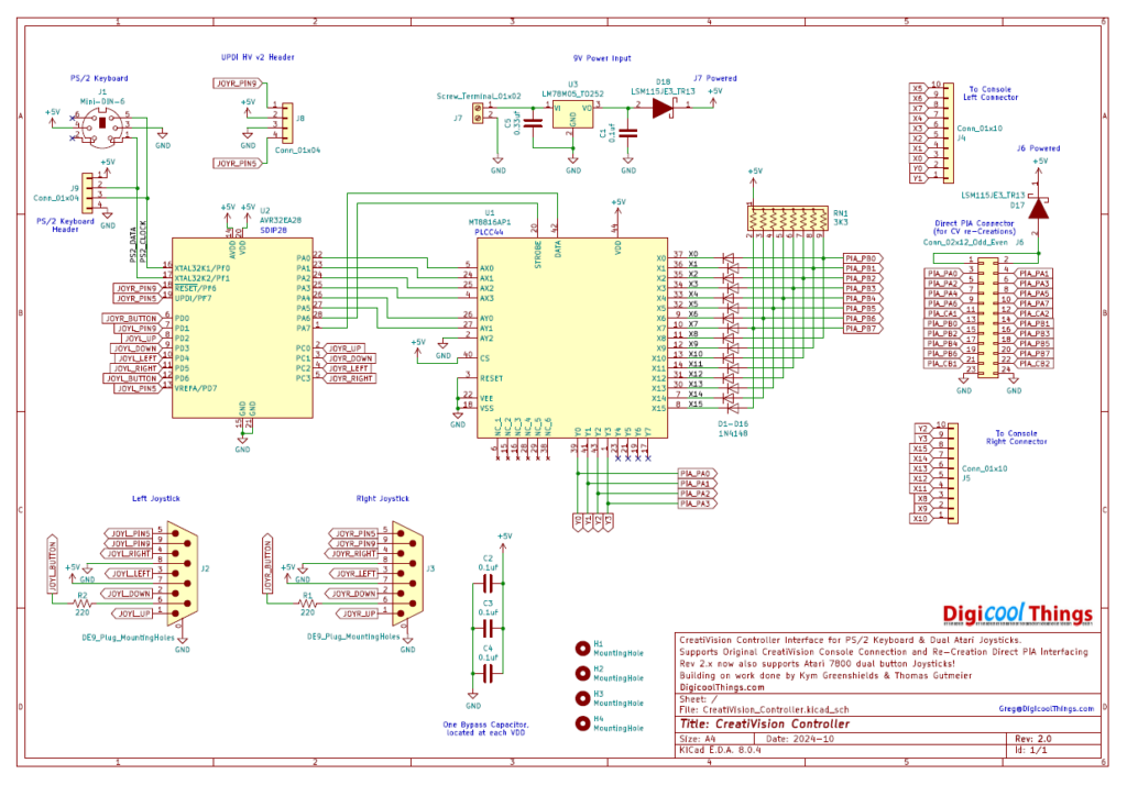
From the schematic you can see that the circuit is actually simplified from v1.2, as we’ve managed to remove all of the jumper headers.
Here is the 3D PCB render.
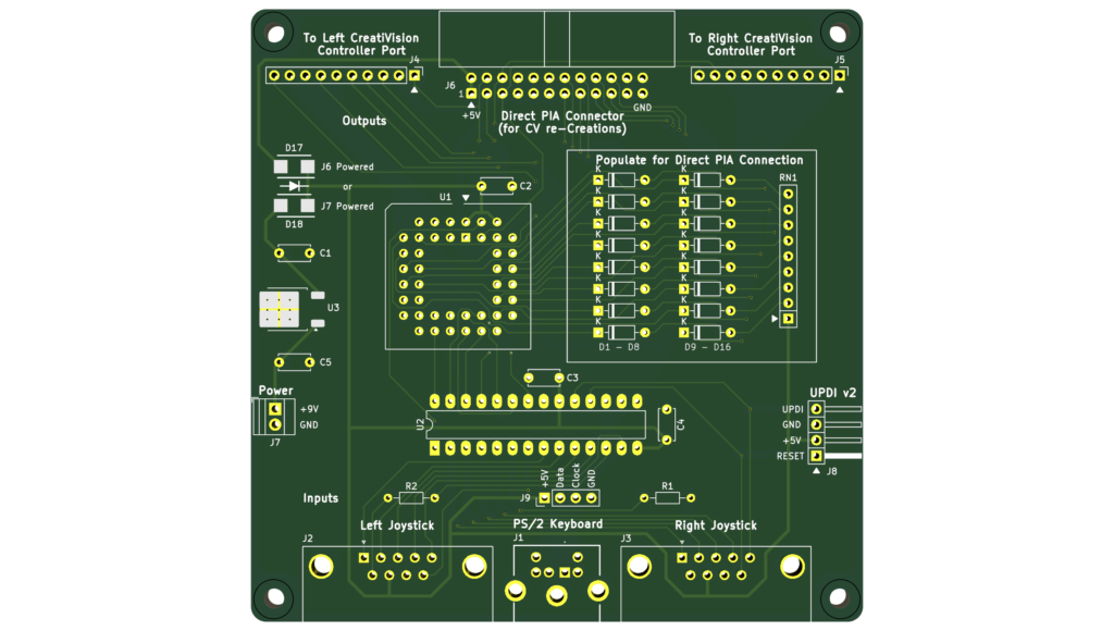
Firstly, you’ll probably notice that the entire reset circuitry, including the reset control jumper headers, have been removed. Software reset of the MT8816 has proven reliable, so the MT8816 hardware reset pin is now permanently tied to GND.
You’ll also notice that the Pin5 / Pin9 second button selection jumper headers, on both joystick ports, are also now gone.
The software now detects the presence of a Atari 7800 dual button joystick, and for regular original Atari compatible joysticks, a second simple button connected to either Pin 5 or Pin 9 will automatically be used as a second button. So, no jumpers are required!
I’ve also now connected 5V to the joystick connectors. I had left this pin unconnected previously, as not being needed, but it occurs to me that the wireless CX78+ dongles will undoubtably use the 5V pin for powering the wireless functionality.
Next, the UPDI v2 standard 4 pin header now connects the microcontroller UPDI HV required Reset pin, on pin 1 of the header (which was previously not connected), as this is needed for the full UPDI HV support.
With the reset circuitry removed, I’ve also moved the UPDI port over to the other side of the board to better use the available PCB space.
You’ll also note the previous USB-C Power Module, has been replaced with a 78M05 linear regulator and appropriate bypass capacitors.
The chosen 5V regulator, in a TO-252 package, is good for up to 500ma. The Controller board doesn’t draw much current at all. However, the unknown factor is the power needed by a connected PS/2 keyboard and also any DB9 attached wireless joystick dongles.
A smaller TO-92 packaged 100ma capable regulator could have been used, but, given the PS/2 Keyboard standard allows for up to 100ma, for driving the keyboard, I decided it was safer to go with the more capable 500ma regulator.
Finally, you’ll note the addition of two protection resistors on the Joystick ports (R1 & R2). These are to protect the port pins which now act as bidirectional pins when detecting and reading Atari 7800 two buttoned joysticks.
So, with the v2.0 changes explained, let’s get one assembled to prove it in operation.
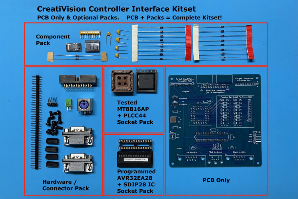
Note, as previously mentioned, the Microcontroller is now an AVR “EA” family device, in the same 28-pin DIL package. And the firmware code is now v2.0.
I’ve uploaded both the original “DA” family v1.0 code (for the v1.x PCB), as well as the new “EA” family V2.0 code (for the v2.x PCB), to the CreatiVisionController GitHub repository.
Also, for those who previously bought a v1.2 based kit-set, from my Tindie Store, I have already sent you a free repeat of your order for the new v2.0 Controller. Given the major changes and new support for the Atari 7800 two button joysticks, and it being only a month since releasing v1.2, I thought this was the right thing to do.
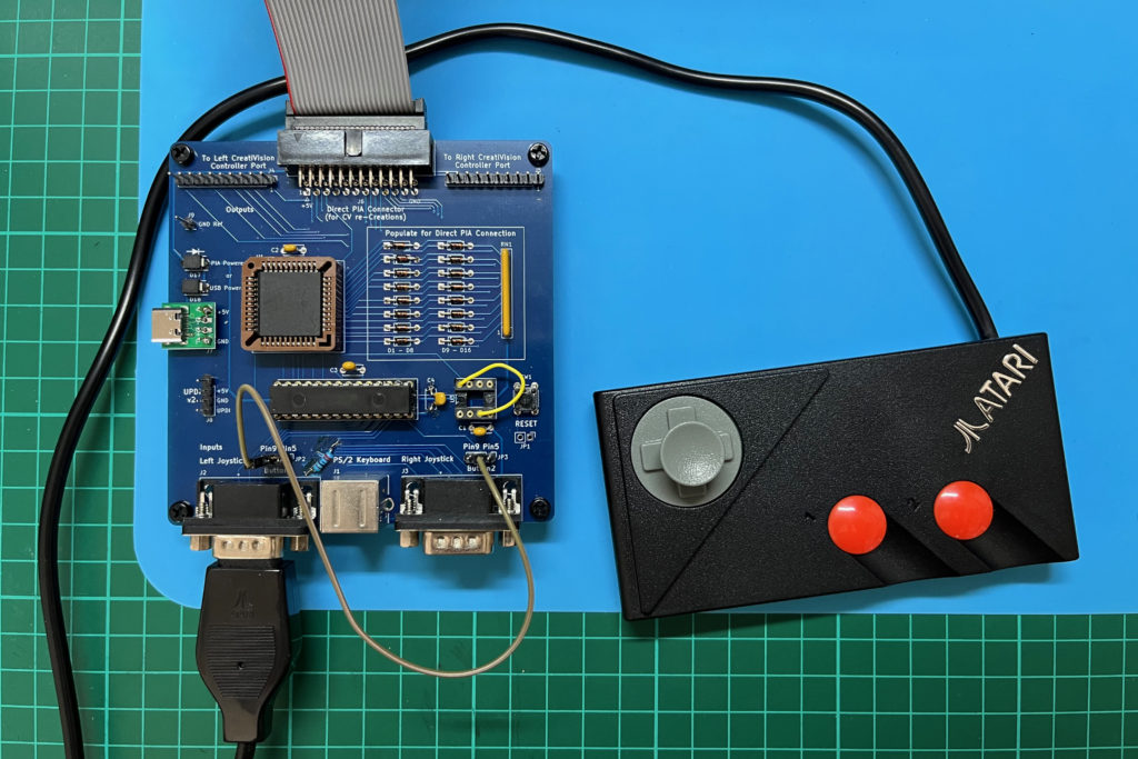
Below is the first assembled v2.0 CreatiVision Controller.
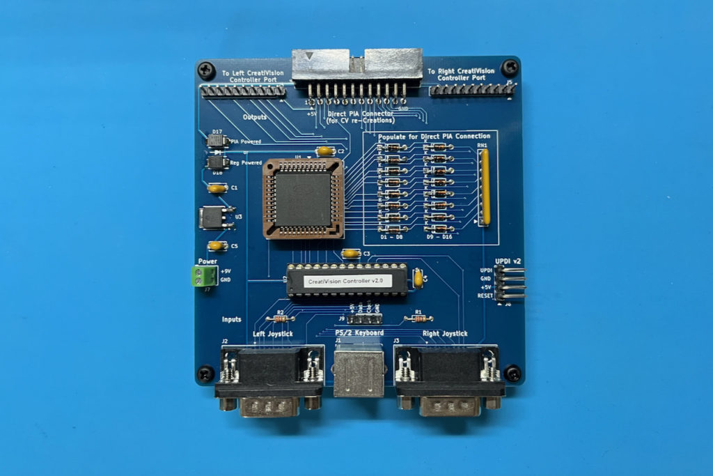
As I did in Part 2, I first connected it up to an original CreatiVision Console.
The difference this time being that instead of a ground reference connection and a separate USB power supply, I’ve just connected the new power terminal to the ground and 9V output pins of the cassette port.
So we now have all-in-one power! So, the Controller interface is now also powered by the CreatiVision Console’s On/Off switch!
I also plugged in a PS/2 keyboard, and my new Atari CX78+ Joypad (plugged into the left joystick port).
I then powered-up with the controller Diagnostic B selected on my MegaCart.
Watch the video if you want to see this setup in use, and see the 2 button Atari CX78+ joypad in operation, automatically detected, and both buttons working!
Awesome!
Next, I changed over to my CreatiVision re-Creation.
In this case, power is supplied via the PIA connector (as already seen in Part 2), and again.
First I powered up with BASIC 1983 running, so we could see the keyboard in real use.
Then, I powered-up again with the “controller” Diagnostic B cartridge selected.
Once again, on the video you get to see the dual-button Atari CX78+ automatically detected and in full 2 button operation.
So, I’m really happy with my version 2 CreatiVision Controller, which I believe now finally delivers the ultimate CreatiVision Controller interface.
Teaming it up with the new Atari CX78+ joypads is really awesome, and I already have my pre-order in for the Wireless Atari CX78+ joypads, when they get released in late November.
If you’d like to have as much fun using my v2 CreatiVision Controller interface, as I’ve had designing it, be sure to take a look at my Tindie Store listing.