
In Part 1, where I introduced my MECB based CreatiVision re-Creation, I ended the post / Video with the CreatiVision Sonic Invader game running successfully in Attract mode.
At that point, the next step was for me to create an Interface to allow connecting a Joystick, so that I could actually play the games!
Join me as I take you through my CreatiVision Controller design journey, including several oversights and lessons along the way. Ultimately, with me demonstrating the use of my resulting Controller Interface on both a real CreatiVision Console, and on my MECB re-Creation!
After a bit of research, I decided that I might as well implement a full CreatiVision Controller Interface, to support both Left & Right Joysticks, as well as a Keyboard. This would then allow full use of the available CreatiVision software, including using the BASIC cartridge.
I also decided, why stop there? It seemed logical that if I was going to all of the effort to create a full CreatiVision Controller Interface for my CreatiVision re-Creation, that I should design it so that it would also work with an original CreatiVision Console.
No doubt, there are owners of original consoles who would like to be able to play the games with a more robust joystick, and also be able to utilise a better keyboard than what the original controllers provided.
So, this is where my CreatiVision Controller journey started.
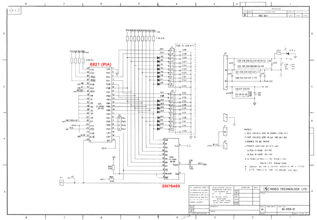
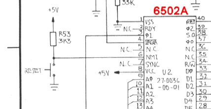
To start with, I already had the original CreatiVision schematics, so I was aware of how the Console’s controllers were interfaced to the 6821 PIA.
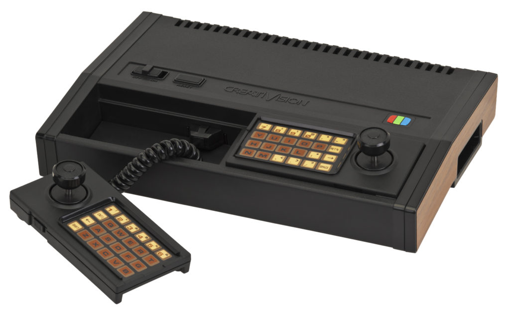
However, this had left an initial question in my mind, as I knew that the CreatiVision controllers included a 48 key QWERTY keyboard, as well as two Joysticks.
From my past experience, it was immediately apparent that there was something extra going on.
You see, the schematic shows the controller interface uses PIA Port B, and only 4 lines of Port A (pins PA0 to PA3).
For a typical scanned matrix keyboard, this would typically allow for 32 key switches to be scanned (if used as a matrix of 8 rows by 4 columns).
Not enough for 48 keys plus 2 joysticks!
So, I did some research on the CreatiVEmu Forum. This Forum hosts an awesome group of CreatiVision enthusiasts.
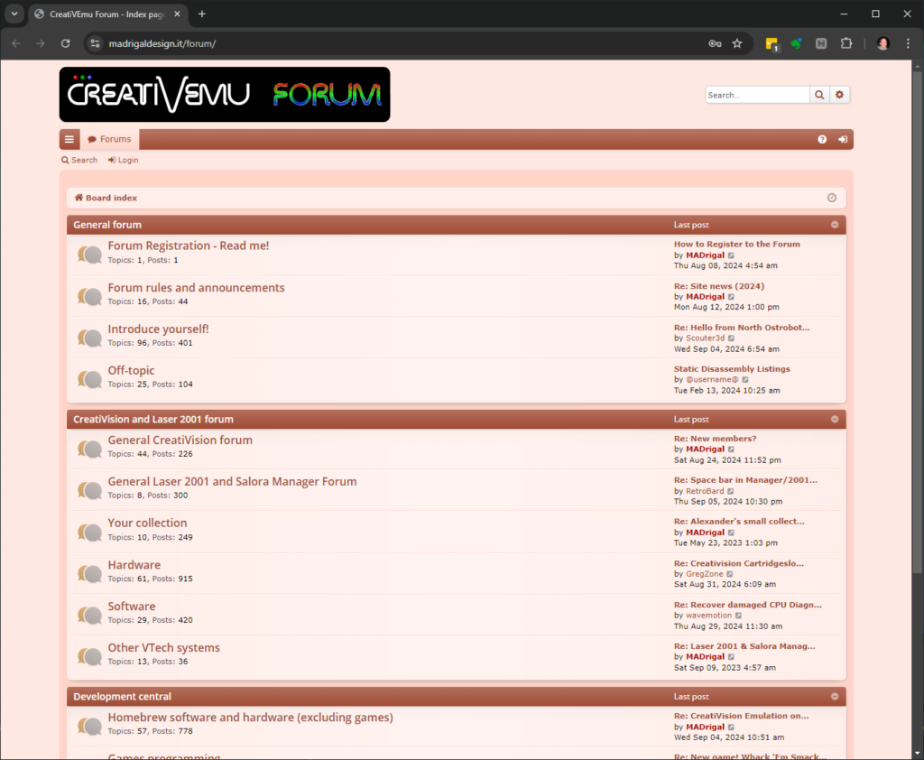
From the Forum discussions, I was able to ascertain a number of crucial and time-saving pieces of information.
Firstly, that the CreatiVision controllers use double-pole switches. This dramatically increases the number of combinations possible in a simple 8 x 4 switch matrix.
So, 48 keys and 2 joysticks from an 8 x 4 matrix now made sense, although it certainly complicates the interfacing!
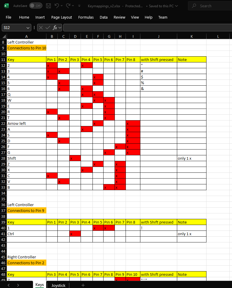
Secondly, someone on the Forum had already mapped the left and right controller port pins, which are used for each controller’s keyboard and joystick switches.
A spreadsheet was shared with their excellent key mapping results.
This was a huge time-saver, and also was crucial for someone who (at that point), didn’t even have their own original CreatiVision Console to study.
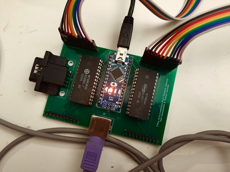
Thirdly, a couple of members of the Forum had already put together a PS/2 Keyboard interface, which also featured an input for one Joystick.
Their interface was based on an Arduino Nano board and a couple of MT8808 28-pin Dual In-Line Package (DIP) Analog Switch Array chips.
These three pieces of information provided all that I needed, to be able dive straight into my own design.
Firstly, I decided that instead of using two MT8808 Analog Switch Array chips, I’d instead use a single MT8816 Analog Switch Array chip.
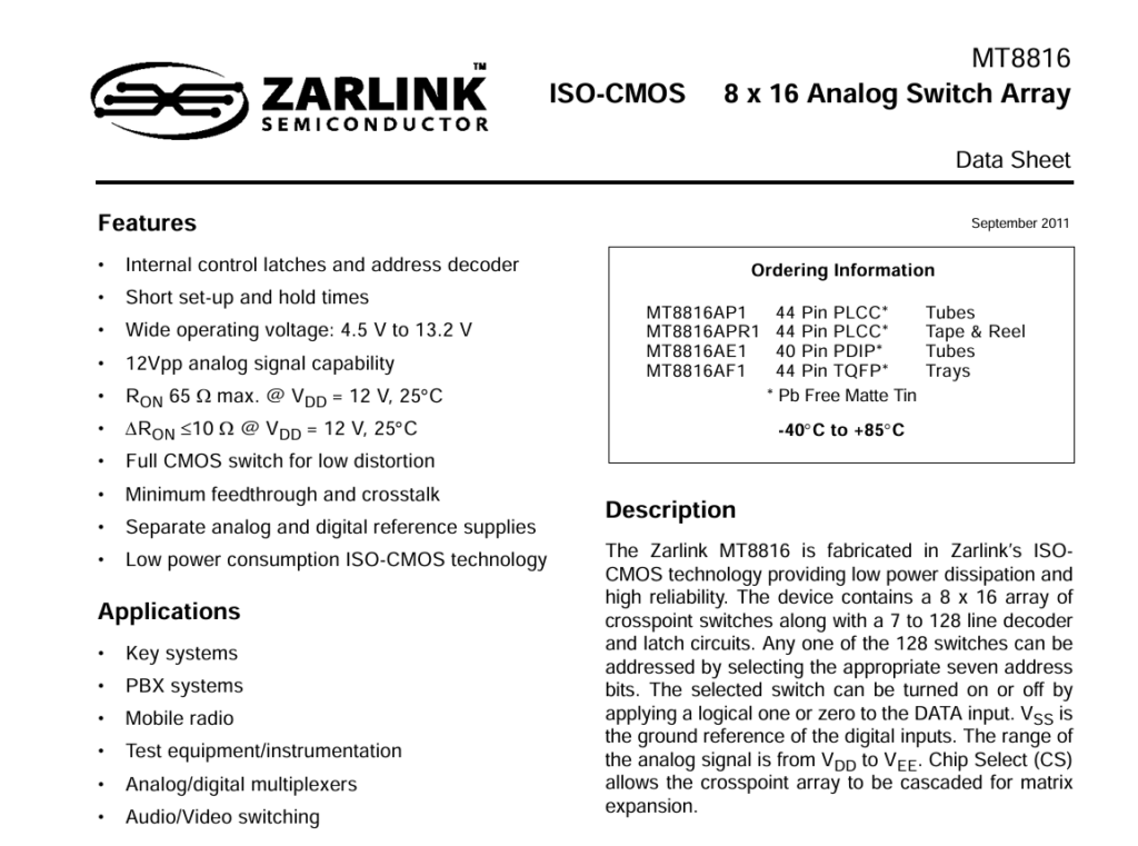
The MT8816 provides an 8 x 16 array of analog switches, as opposed to only an 8 x 8 array on the MT8808.
Perfect for interfacing to the two controller ports of a CreatiVision Console.
Also, not only are the MT8816 devices still in-production in a more compact PLCC44 package, which are still retro friendly thanks to Through-Hole (TH) PLCC sockets, they’re also cheaper to source than just a single MT8808 in the larger DIL package.
Secondly, I also decided that I didn’t want to use an Arduino board in my design. Instead, I wanted a compact and cleaner solution, designed around using an on-board microcontroller chip.
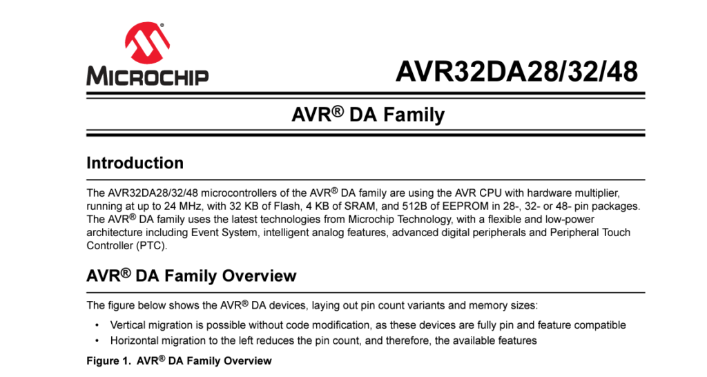
Based on the number of I/O pins required, 5V logic, and my desire to stick with Retro friendly Through-Hole (TH) components, I decided to go for a “retro appropriate” 8-bit microcontroller chip, in a 28 pin DIL package.
Specifically, I really like the newer “DA” family of 8-bit AVR microcontrollers.
Because I like a challenge, I also decided I’d start from scratch with developing the required Controller firmware, including for the PS/2 Keyboard interfacing.
This is mainly because most pre-written PS/2 keyboard interface libraries are designed for use at a higher-level.
To most realistically interface a PS/2 Keyboard to the CreatiVision, it makes more sense to go to the lower-level of mapping the actual key-down and key-release events of the PS/2 keyboard, to the CreatiVision Controller’s actual keyswitch closing and opening.
This makes for the most realistic and accurate functional replication of the CreatiVision’s own Controllers, and therefore should be fully compatible with different software’s use of the controller keypads.
Of course, whichever way you decide to interface a PS/2 keyboard, has it’s compromises.
If you were to interface at a higher-level, by mapping translated keyboard ASCII characters to the CreatiVision’s key-strokes, you could achieve a mapping of actual PS/2 key characters to their CreatiVision key equivalents.
But, this would be at the compromise of not truly replicating the actual key-press and key-release, of the individual switches in the original controllers.
By instead interfacing at a lower-level, we can accurately replicate the original controller key actions, but with the compromise that we must allocate an actual PS/2 keyboard key to be the equivalent of a CreatiVision key.
This is fine for the majority of the keys, but some keys, for example the colon and semicolon, are on separate keys on the Creativison, but are a single combined shifted key on the PS/2 keyboard layout.
But, I consider this, the lesser compromise. It is much more important to replicate the actual CreatiVison key actions! Non-matching PS/2 keys can either be remembered, re-labelled, or even a custom keyboard implemented (but more on that later).
So, with my plans now solidified, it was time to start on writing the firmware, and also some breadboard prototyping.
I decided to start with the PS/2 keyboard interfacing, as this was core to the overall Controller Interface functionality. Even though I just wanted to play a game of Sonic Invader!
First off, I decided on an Interrupt Driven keyboard interface, as being the only way to go.
Interrupt driven enables writing a 100% reliable Keyboard interface!
So, I started by writing an Interrupt Handler, to receive properly formatted PS/2 keyboard scan codes, and store them in a circular buffer, for subsequent access by the main controller program loop.
Here’s the Interrupt Service Routine that I came up with.
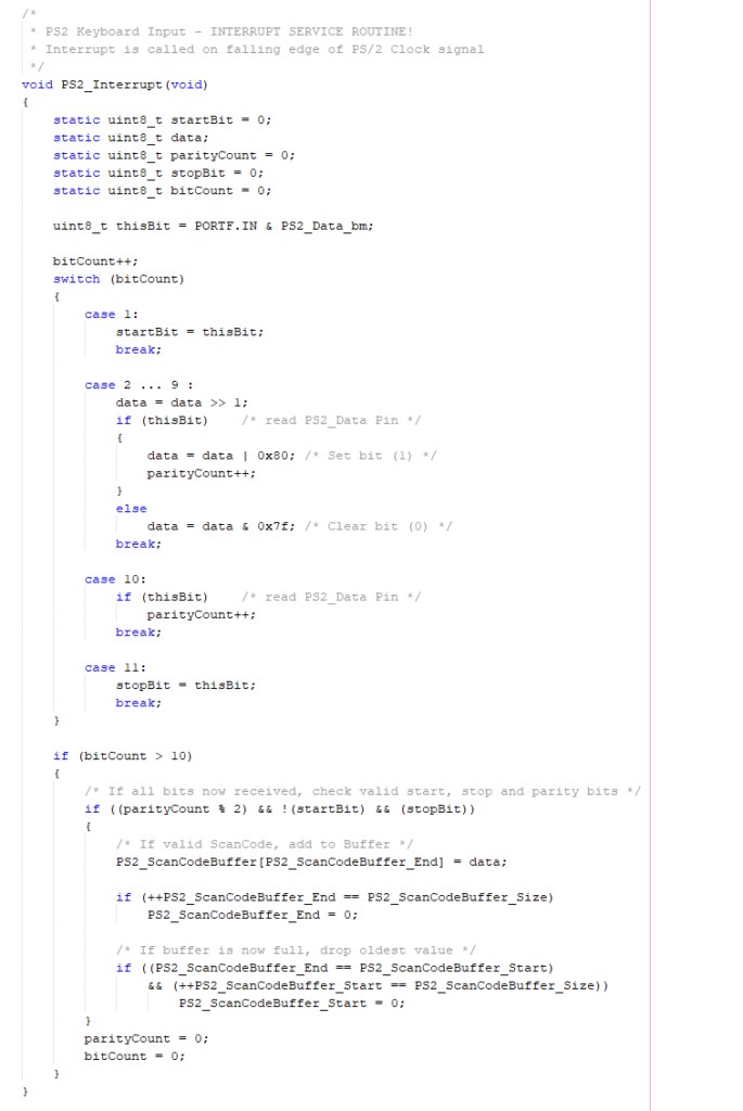
The Interrupt Service Routine is triggered by the falling edge of each PS/2 clock signal transition. I then capture all 11 bits of a PS/2 scancode transmission, and then verify the transmitted scancode structure, to ensure that I have an appropriate level start and stop bit, and I also calculate the parity bit to ensure it is the correct odd parity, in addition to capturing the 8 data bits.
Only with a valid received scan code byte, do I then store it in the received scan code buffer.
Pretty robust!
Now to debug this code on my AVR microcontroller chip. So I hooked up an AVR microcontroller’s 8-bit PORT A to one of my “8-bit LED Things“, and I wrote a very simple Main Application loop that simply retrieves the next scancode from the buffer and outputs it on PORT A, then delays for 1 second.
Therefore, I can now see all of the captured key presses and key releases displayed sequentially on my 8-bit LED Thing, so I can assess if my code is working correctly.
Take a look at the linked Video, if you’re interested in seeing this in action.
With this proven, I then dived in to designing my first prototype PCB.
In the distant past I always fully developed and proved new digital hardware on a breadboard prototype, before moving to PCB design.
That was just the way we had to do it, back in the day, when PCB design and PCB manufacture was time consuming and expensive.
These days, with the advent of great free PCB design tools, like KiCAD, and relatively low cost PCB manufacture, it actually now makes more sense to go straight to the PCB design stage, for your final prototype design.
This also fast-tracks your project by getting into the PCB design stage earlier, even if several revisions are required.
Now, this project turned into one of those “Several Revisions Required” exercises.
For my first PCB revision, I was caught out by a few, lets call them, “Oversights“.
Firstly, I made the incorrect assumption that the CreatiVision key mapping, which I’d obtained in a shared spreadsheet from the CreatiVEmu Forum, correlated to the Controller Connector pin numbers as labelled on the official CreatiVision schematic!
Unfortunately, this was not the case. It turns out that the spreadsheet pin number references are the reverse of the schematic connector pin numbers.
Here is the comments I’ve put in my source code to explain this.
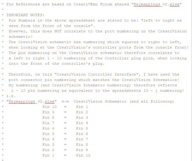
Essentially, for the two 10-pin Controller connectors, pins 1 to 10 as shown in the CreatiVision Schematic, actually correlate to pins 10 to 1 in the key mapping spreadsheet.
So, pin-10 in the spreadsheet refers to pin 1 on the schematic, etc.
Secondly, the KiCAD mini-DIN footprint, that I’d obtained for the PS/2 connector (via Mouser), was reversed.
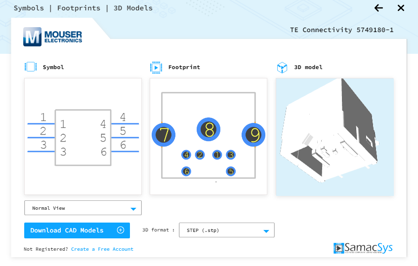
As a result the PS/2 power pins were reversed, resulting in me frying my only compact PS/2 keyboard. So, a replacement keyboard had to be ordered.
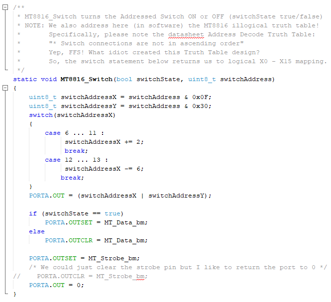
Lastly, I completely missed the illogical sequence in the Switch Matrix Address Truth Table in the MT8816 datasheet.
This one actually left me completely gob-smacked!
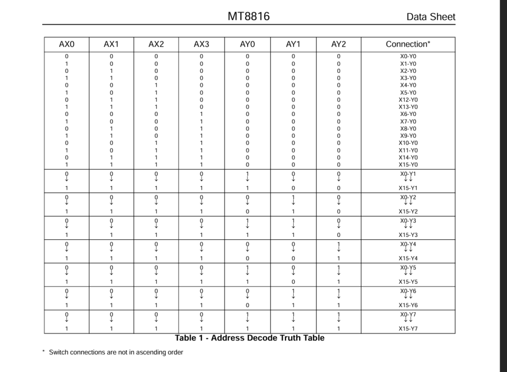
I always thoroughly read Datasheets. They are a designers bible!
But this one got by me, as it makes no sense at all. The truth table anomaly is only highlighted by an asterisk and a vague comment.
Furthermore, the only reason for this anomaly (that I can ascertain), is that the IC’s pinout must have already been published and locked-in, otherwise it would have been much more logical to just re-label the pins so that the truth table was in an expected logical sequence.
Anyway, for this last “oversight“, I ended-up resolving the illogical mapping in software, therefore retaining the logical PCB MT8816 pin labelling sequence.
The first two “oversights“, did however require a rework of my schematic, software, and a rework of the PCB.
Having obtained my second prototype PCB, and with some more work refining the software and manually re-mapping all of the spreadsheet key-mappings to their actual CreatiVision schematic controller port pin numbers, and their associated PIA Port pins, I finally had a working prototype!
Finally, I then further revised the PCB to revision 1.2, to include a header for the PS/2 connections (more on that later), and also a header to determine if we are using the hardware reset circuitry, which I had included in the schematic.
As it turned out, I can effectively software reset the MT8816 switch array on power-up, and I haven’t once needed to reset my microcontroller during my testing.
I’ve kept the hardware reset circuit on the PCB, just in case. But, essentially, it doesn’t need to be populated.
Okay, so lets look at my eventual revision 1.2 schematic.
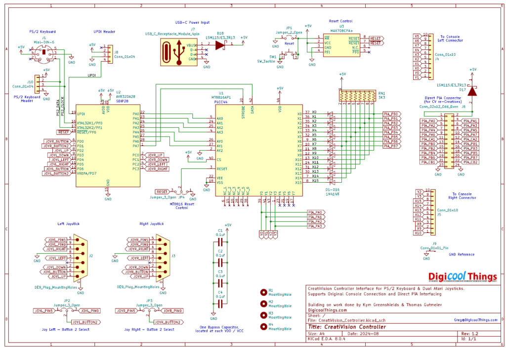
As you can see, it makes for a quite compact, basically 2 chip only design, catering for both original CreatiVision Console connection and also for use with a direct PIA connection for CreatiVision re-Creations (like my MECB system).
For supporting re-Creations, I have effectively duplicated the original CreatiVision’s PIA Port diode isolation and pull-up resistors on my Controller Interface, allowing it to be connected directly to a PIA’s PORTB and PA0 to PA3 of its PORTA.
So, it’s perfect for interfacing straight to a PIA, for any CreatiVision re-Creation!
The PIA Port connector I used matches my MECB Motorola I/O Card 24-pin IDC connector, which carries all the PIA Ports and also GND and 5V. This allows my CreatiVision Controller Interface to also be powered directly from the MECB Motorola I/O Card itself.
For using the Controller with a real CreatiVision Console, I’ve included a USB-C Socket Power Module, for a USB-C power source, and also (crucially) a ground reference header pin connection.
Unfortunately, the CreatiVision Console’s controller ports do not include a Ground reference. In addition, the CreatiVision’s AC Power Supply is not earthed, so the only chance of a common earth referenced ground would be perhaps via your display connection.
For reliable use, you therefore need to connect the ground reference header connection to your CreatiVision Console.
To do this, externally, there is a ground pin available on the CreatiVision’s left-side Cassette Deck connector.
As a warning: Apart from earlier frying a PS/2 keyboard, I also managed to damage one of my MT8816 chips, when I forgot to ground reference the connected devices.
Everything was working for a few sessions, then perhaps I connected-up or powered-up in a different order, as a number of keys stopped working when I powered up one day.
It appeared I had managed to damage one of the MT8816 chips switch ports, which could have only been due to the floating / isolated ground level between the two devices.
Since then, I’ve ensured the Ground reference is connected between the CreatiVision Console and my CreatiVision Controller Interface, and I’ve had no more problems!
I imagine another option (instead of the side connector ground connection), may to be to investigate whether you could install the CreatiVision Controller inside the CreatiVison Console’s case, although it’d probably be a tight fit!
Or, alternatively, solder in a ground connection wire (or connector), to feed from the back of the Console. But, it’s over to your creativity really. Just make sure your connected devices share a common Ground!
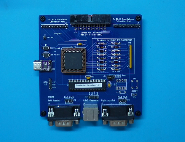
So, lets now take a look at the latest revision 1.2 PCB layout. Here is a 3D render of my PCB.
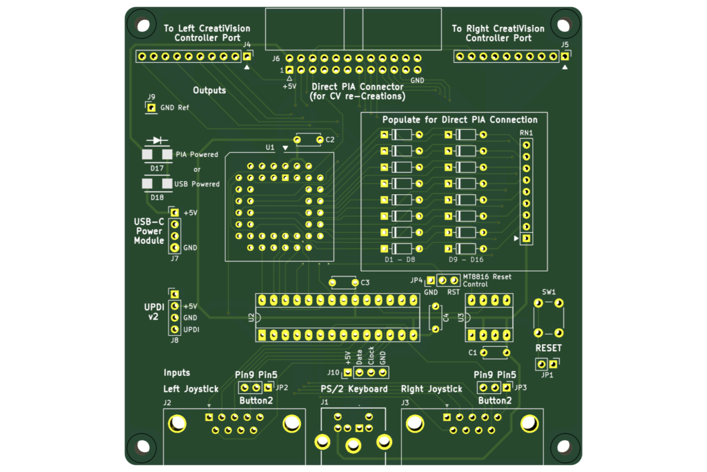
I think it looks really awesome. But then I do really enjoy, and spend too much time on, PCB layout!
As you can see, there’s plenty of silkscreen labels to clearly identify all of the connectors etc.
Everything is TH (Through-Hole), for easy assembly, with the exception of only two surface mount components. These are the two large ultra-low forward voltage Schottky diodes, which isolate the two alternative power sources. Although these are surface mount, they are plenty big enough to allow for very easy hand soldering.
The Atari Joystick DB9 interfaces also have jumpers for selecting a second button connection on either pin 5 or pin 9 of the BD9 connector.
On an original Atari joystick, or a C64 joystick, these pins are normally the analog paddle controller inputs, but on some later DB9 Joysticks these are used for a second (or third), button connection.
Often, these joysticks have a switch to allow enabling or disabling these extra button connections.
The original CreatiVision Controller joysticks have 2 buttons, so a simple 2 button capable DB9 joystick is recommended, if you have one.
Other than this, note that the original CreatiVision Joystick supports 16 directions, whereas an Atari DB9 Joystick only supports 8 directions. Whether this really affects your gameplay is probably subjective. But, I’m okay with it.
The other thing of note that I’ll mention, is that I’ve also written the firmware to be as low latency as possible.
Specifically, there are absolutely no software delays implemented in my code, anywhere. Joystick actions and Keyboard key presses are serviced in a tight loop.
So, when you use the joystick, your joystick actions are translated to CreatiVision Joystick switch actions virtually instantaneously. Also, when you press a PS/2 keyboard key, the only latency, before the CreatiVision keyboard key is also engaged, is the time taken for the PS/2 scancode transmission from the keyboard for the key-down or key-release event. Perfect!
Okay, so here’s a photo of one of the first revision 1.2 PCB’s fresh from manufacture.
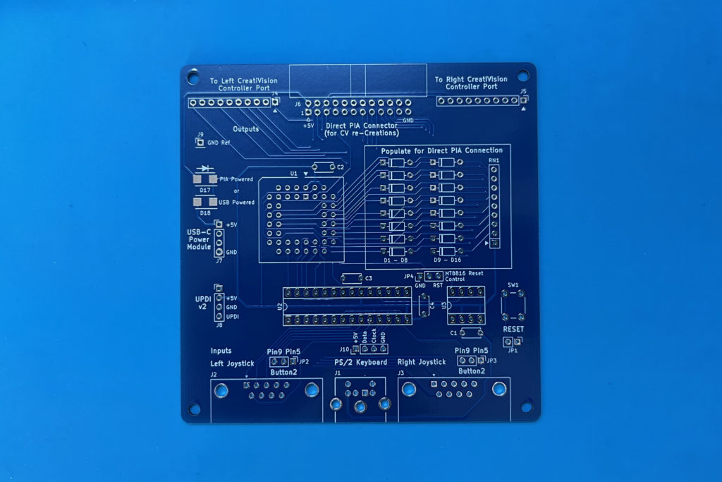
I’m pretty confident it’ll work first time, as it’s just a fine-tune from my revision 1.1 prototype, as I’ve already described.
So, lets get one assembled.
And here is the first partially assembled board, with it’s two main chips installed, and just the reset jumper to ground, as I haven’t installed the reset circuitry.
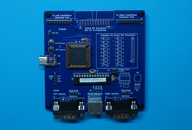
I also haven’t yet installed the diodes and the pull-up resistor network, to support my CreatiVision re-Creation.
This is because I thought I’d start-off by showing the minimal assembly required for use with a real CreatiVision Console.
If you were only intending to use this Controller Interface with a real CreatiVision Console, then the diodes and resistor network are not needed, as I’ve clearly noted on the PCB silkscreen. The 24-pin IDC connector is also not needed.
For testing this with a real CreatiVision Console, there’s also a bit of a story.
You see, I missed the opportunity to get my hands on a CreatiVision Console a few years ago, which is what also prompted me to explore my old TMS9929 chips, develop my Alternative “low pin count” VRAM solution, and to make my MECB based CreatiVision re-Creation!
But, as luck would have it (and very timely for my current project), recently another CreatiVision console came up for sale locally.
This was the first one to appear on my watch-list in several years. So I jumped on it, knowing it’s just what I needed for final testing of my new Controller interface.
Here is a photo of my CreatiVision Console fully hooked up for testing.
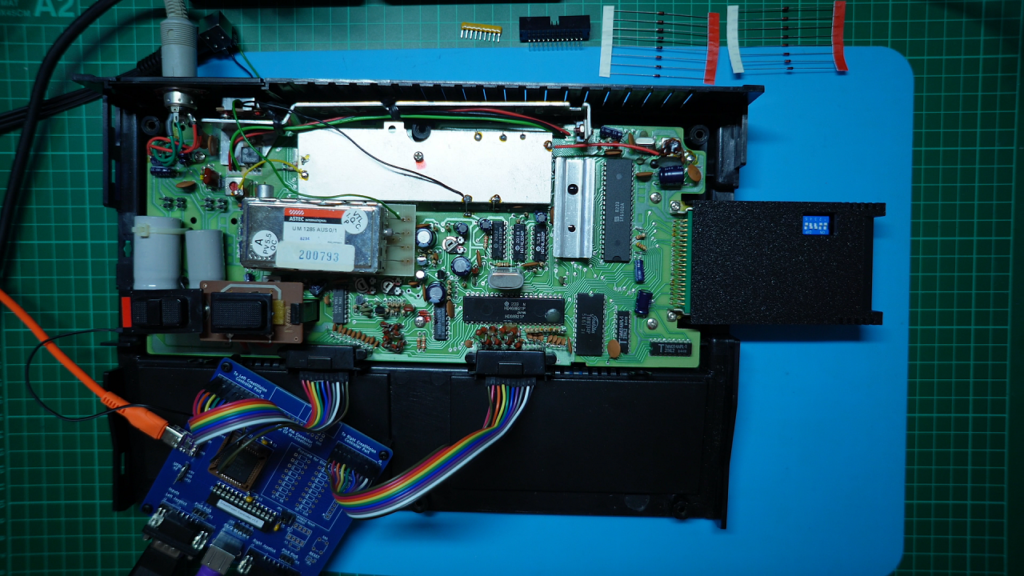
As you can see, I’ve plugged in a couple of 10-way Dupont jumper leads to the controller port pins to connect across to the Controller PCB headers.
And, as discussed earlier, don’t forget a Ground reference connection to your Console.
I’ve also used a USB-C Power feed, to power the interface board.
Finally, I’ve also plugged-in a PS/2 keyboard, and a Joystick into the left Joystick port.
Be sure to watch the Video, if you’re interested in seeing the original Console use demonstrated.
Unfortunately the Composite Video output of my console was quite noisy on my video monitor. So, I probably also need to to think about upgrading it with a TMS-RGB module. But the noisy video is fine for this Controller Interface usage demonstration.
If you’re a real CreatiVision Console owner, you might have noticed that I have a MegaCart plugged into my Console.
I made myself a new MegaCart for the CreatiVision Console, which includes all three of the original VTech Diagnostics. Noting that “Diagnostic C – CPU”, was just recently recovered and shared on the CreatiVEmu website in August 2024.
I’ve revised the Schematic and PCB layout of the earlier published MegaCart, revising it to version 1.2
You can find my revised MegaCart KiCAD schematic, PCB design, and gerbers, on the DigicoolThings github, together with a full description of my changes.
My CreativisionMegaCart repository is forked and revised from the original github project, and is licensed under the same Creative Commons Attribution and Share Alike license (CC BY-SA).
With all three diagnostics available in my new MegaCart, I also switch to the Controller Diagnostic B, for Controller testing (see the video).
So, with the Controller tested on a real Console, next I add the CreatiVision re-Creation supporting components.
Okay, so as you can see, I’ve now added the 16 diodes, resistor network, and 24 pin IDC connector, to support CreatiVision re-Creation direct PIA connection.
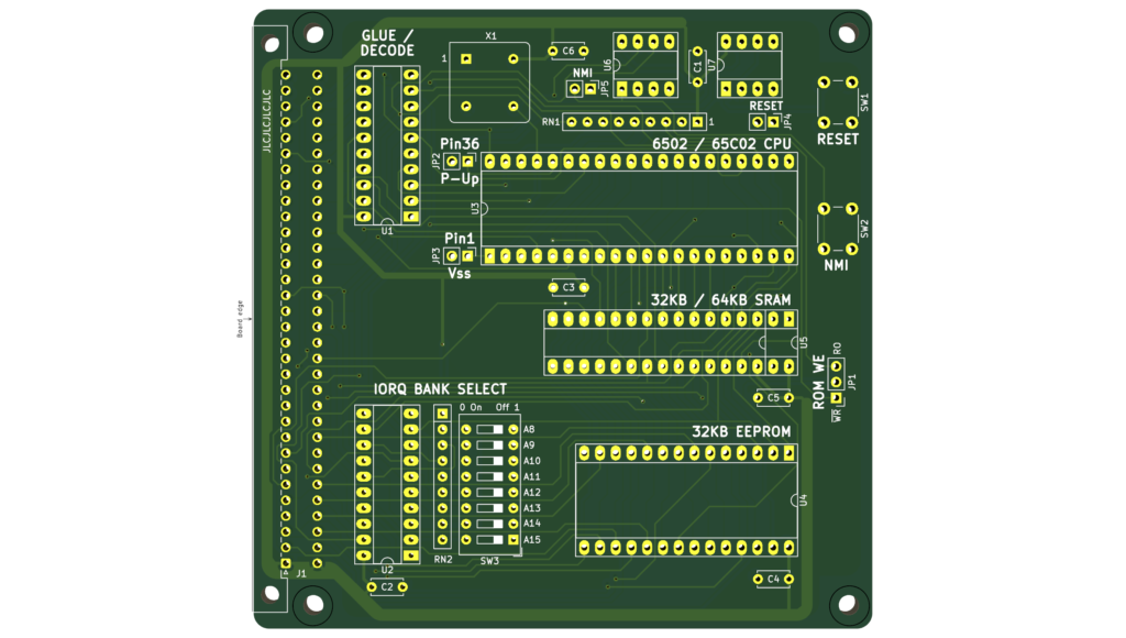
As a re-cap, particularly for anyone new, who hasn’t been following along with my MECB project, let’s take a quick look at the MECB components of the project.
Here are all the Cards laid out.
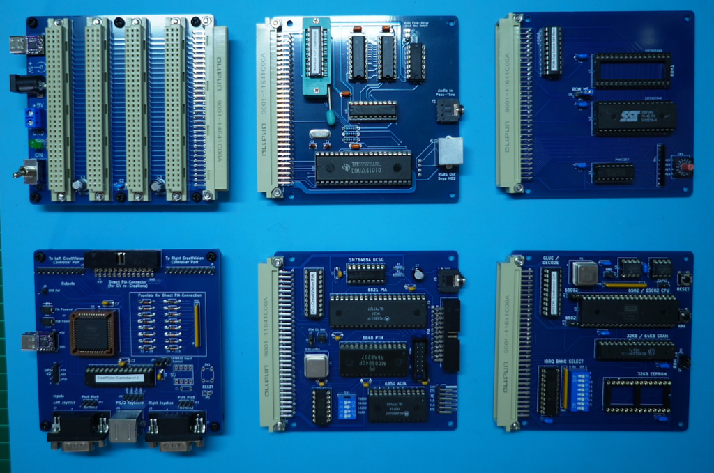
First we have the MECB Backplane, which provides the Card mix-and-match capability for building a MECB based system.
Then, we have the Motorola I/O Card with sound. This features the Motorola PIA chip, ACIA chip, and also the Motorola PTM chip. i.e. Parallel and Serial I/O, as well as three timers.
In addition the I/O Card has a SN76489 Digital Complex Sound Generator.
For the CreatiVision re-Creation we’re only using a MC68B21 PIA and the sound chip. So, we could leave the MC6850 ACIA and MC6840 PTM chips unpopulated.
Next, we have the TMS VDG Display Card. This was designed with my low pin count alternative VRAM
solution that I devised. See my earlier blog posts/ videos if your interested in this journey.
The Video Card also has a audio pass-through input socket, to allow feeding the sound chip’s output through the video output connector (if desired).
Next we have a MECB 1MB Bank-Switched ROM Expansion Card, which enables switching up to 16 banks of up to 64K of ROM space.
At the moment I’ve just got one 512MB ROM installed, which allows 8 banks to be switched between.
Finally we have the 6502 CPU Card. For this project I’ve left off the ROM chip, as the ROM is all handled by the 1MB ROM Expansion Card.
So, that summarises the MECB based modular hardware, with it’s memory map configured for our CreatiVision re-Creation, as was presented in more detail in Part 1.
For my MECB based CreatiVision re-Creation, I’ve also made-up a 30cm IDC24 one-to-one cable, to connect the new Controller Interface to my MECB Motorola I/O Card PIA connector.
As mentioned earlier, this connection also powers the CreatiVision Controller PCB.
As before I’ve also plugged-in a PS/2 keyboard, and a Joystick into the left Joystick port.
Now, there’s one more discovery I made, which I’d initially overlooked when studying the CreatiVision schematic.
That is, that the CreatiVision’s “RESET” button, which must be pushed in order to start a game, is actually connected to the 6502 NMI input (non-Maskable interrupt).
It is not a actually a hard Reset!
Because of this, I initially wired up a NMI link jumper wire, via my MECB Prototype Card header.
However, this was really only a temporary stop-gap measure, to get me up and running.
A NMI link wire is not really ideal. Particularly since your NMI interrupt button should really be de-bounced (even though it isn’t in the original CreatiVision)!
So, to properly resolve this, I’ve also made an update to the existing MECB 6502 CPU Card, to add a debounced NMI push-button and NMI button header, to join the existing Reset push-button and Reset button header. This was covered in my last blog post / video.
But, please note: Since making the updated 6502 CPU Card, and making that video, I’ve posted a “Follow-up” on that earlier blog post.
Essentially, during my testing of Sonic Invader, I noticed that the CPU Card hard Reset button also did actually work for getting me into Play mode. However, this doesn’t detract from the fact that the original CreatiVision Console only has a NMI button for “Reset”.
So, to ensure full CreatiVision software compatibility (and for other 6502 based projects that might require a NMI button), I’m still happy to have now implemented a debounced NMI push-button on v1.3 of the 6502 CPU Card!
Anyway, here’s a 3D render of the updated 6502 CPU Card PCB.
Next, I connect-up the power, video and audio leads, power-up and test it out!
Please see the linked Video to see the CreatiVision Controller with the MECB CreatiVision re-Creation in action!
This was awesome! I was finally playing Sonic Invader again, after all these years, but this time on my MECB based CreatiVision re-Creation, and with a good Joystick and an awesomely sharp display!
Now, another lesson. This one is about the classic saying, RTFM!
You see, during initial testing I thought I had a problem with the Aliens occasionally disappearing from the screen. I thought I had a hardware issue with my display card, and started swapping DRAM and TMS VDG chips on my Display Card.
It was only when I noticed a pattern to this, that I finally RTFM!
You see, I originally thought pressing the fire button, before starting, was incrementing the number of credits for game-play, just like on an Arcade board.
But, it turns out that this was actually selecting 1 of 16 game modes!
I was incrementing the count to 5 before starting a single player game. Fortunately, I finally noticed that the Aliens didn’t randomly disappear if I started the game with a 1 count.
Reading the manual was the answer! It turned out that mode 5 was where the Aliens disappear for periods of time, to add a new challenge to the game!
Problem solved. There was no problem!
After a quick play with Sonic Invader, I then swapped across to the “Diagnostic B” cartridge, which I had earlier demonstrated on the original Console, to enable doing a full CreatiVision Controller test on my CreatiVision re-Creation.
Once again, with all the controller switches present on the screen, I was able to easily test all the key switches and the joystick response.
As expected, all works great!
So, I’m really happy with how my CreatiVision Controller project has come together.
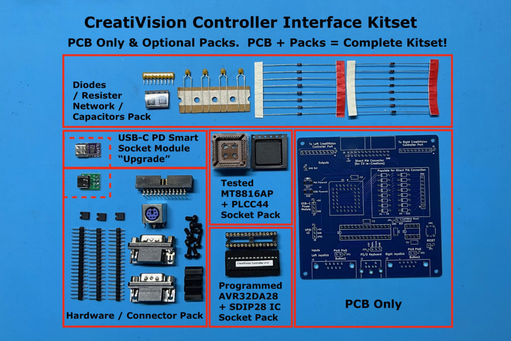
If you’d like one, I’ve now added the CreatiVision Controller to my Tindie Store.
You can order just a PCB, or there are several optional packs to complete your Controller kitset.
I’ve also made the firmware’s C source code available via the DigicoolThings CreatiVisonController repository on github.
I’m pretty thorough with documenting my source code, so it should be very easy to follow!
Now, just before I finish this Part 2, for those who are still following, let me just say it: There’s One more thing …
There may well be a next part, in the future, for my CreatiVision Controller journey.
For a teaser, be sure to watch the linked Video to the end!