
Last year, I made a PLCC packaged version of my 6809 CPU Card. This CPU Card also built in the functionality of the 1MB ROM Expansion Card, taking advantage of the PLCC package PCB space saving.
Now, I do the same for my existing 6502 CPU Card!
Join me as I present the design, then assemble a WDC W65C02S PLCC packaged CPU Card, also have some fault-finding fun, and eventually demonstrate the new Card’s use with the 16 game ROM set for my 6502 CreatiVision re-Creation.
Pre-amble
First off, I have my MECB based CreatiVision re-Creation on my workbench.
In the previous videos that I’ve made which demonstrated my Video Card output, I showed the video output by simply pointing my video camera at the monitor.
This, unfortunately, created issues with reflections from my windows, as well as image focus challenges.
So, I’ve finally got myself another Video Capture card, which allows me to now directly capture my VDP Display Card output.
And, here’s what it looks like:

It’s pretty awesome, and a significant improvement on my camera recorded video screens, of the past! This enables me to share a picture thats more reflective of what I’m actually seeing on my monitor, both in terms of colour and image sharpness.
Introduction
So, back to the main topic of this post / video, for which you’ll also see why having my CreatiVision re-Creation handy is relevant.
As I mentioned above, last year I created a PLCC package based 6309 CPU Card.
The CPU Card made use of the PCB space saved, by using the PLCC packaged CPU, to also include PLCC packaged 1MB ROM Expansion.
This effectively made the 6309 PLCC CPU Card, a combination of the existing DIL package based 6809 CPU Card, and the 1MB ROM Expansion Card.
Not only did the PLCC CPU Card deliver 2-in-1 functionality, it also looked awesome with it’s through-hole socketed PLCC chips.
The new card still remaining through-hole (TH) retro friendly, for easy assembly.
So, I’ve now done the same thing for the existing MECB 6502 CPU Card.
Design
I’ve taken the existing DIL packaged 6502 CPU Card, and made a 2-in-1 combination 6502 CPU and ROM Expansion PLCC package based Card.
Doing this has made for a really nice 6502 CPU Card.
This new CPU Card also benefits my CreatiVision re-Creation project, as this combination card means there’s now one less card required, for a full 16 game CreatiVision re-Creation.
Now, there’s one important thing to note. The pin-out of the original 6502 PLCC package CPU chips, differs from WDC’s W65C02 PLCC pinout.
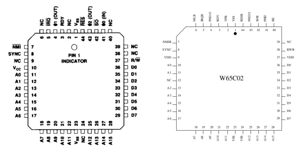
Therefore, I had to choose one or the other. Since the WDC W65C02 is still in production, and therefore easy to source as a brand new part in it’s PLCC package, and it’s also capable of higher clock speeds, I decided that for the PLCC version 6502 CPU Card, I’d go with WDC.
So, here is the schematic. It shares the same improvements, that I implemented in the 6309 PLCC CPU Card.

Be sure to view the MECB 6309 PLCC CPU Card presentation, for full details of the improvements.
In addition, the 6502 card also has the added de-bounced manual NMI switch (and header), that the existing 6502 DIL package CPU Card has.
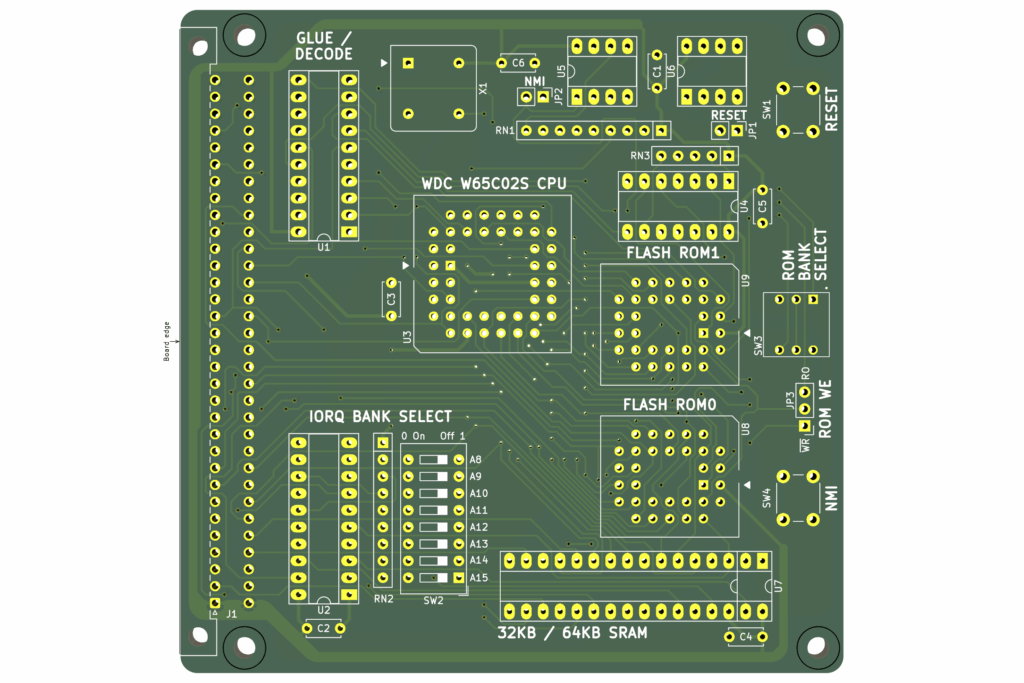
Here’s the 3D render, of the resulting PCB.
Assembly
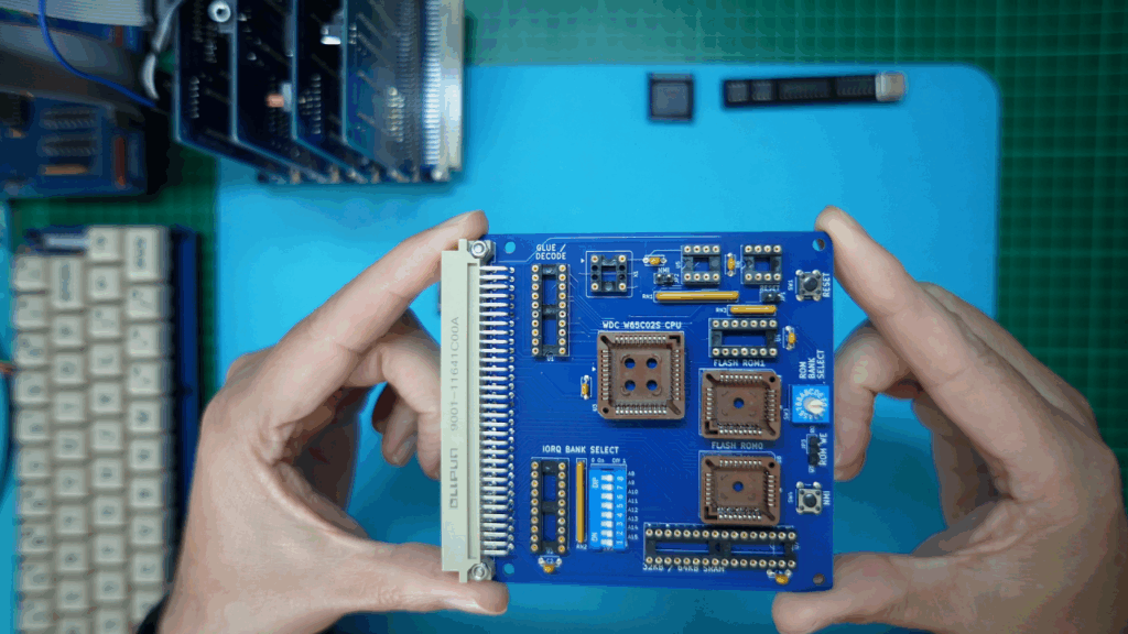
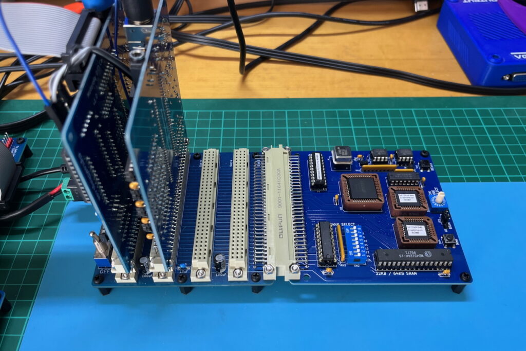
On my workbench, I’ve laid out the PCB and all of the optional component packs, along with the additional required components.
All are ready, for my first card assembly and testing.
For this new CPU card, I’ve decided to do a couple of extra things with my Tindie store listing, in the interests of making your parts procurement as easy & convenient as possible.
Firstly, I’ve expanded the “Optional Pack” offerings, to make the parts that are available from me, more complete.
In this way, you have the convenience of ordering most of the parts, together with your PCB.
Secondly, I’ve made sure that the “Additional components required”, can all be ordered from a single source.
To this end, the Bill Of Materials (BOM), provides all of the part numbers for ordering these additional required parts, from Mouser.
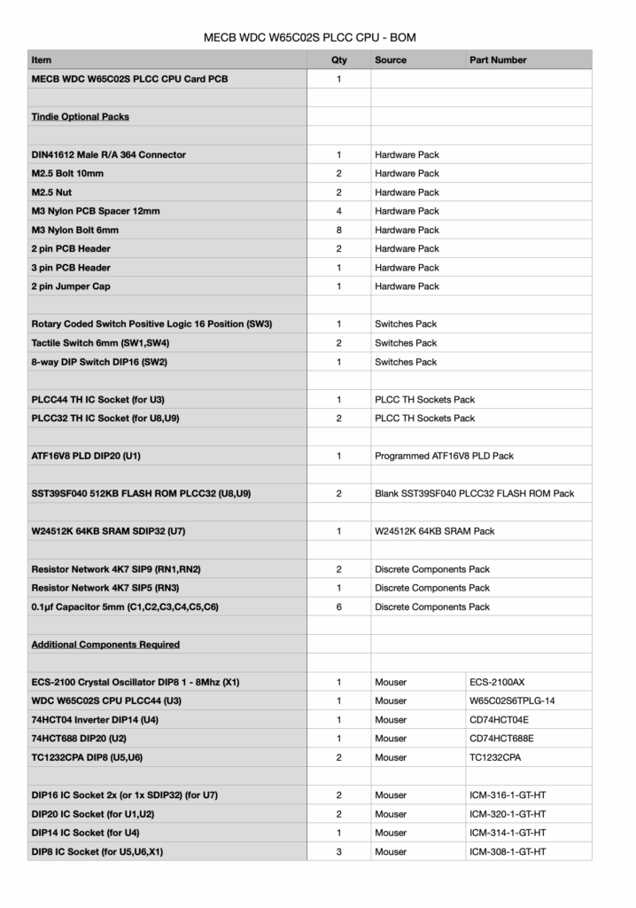
Alternatively, these relatively common parts are perhaps also available from your own preferred supplier, or they may even be in your existing parts storage.
If this added convenience is helpful, I’ll also look at doing the same for my other MECB Card offerings on Tindie.
So, with that update explained, I’ll now dive into getting this new CPU Card assembled.
If you’d like to view my “order of assembly”, be sure to watch the video!
And here is the fully soldered card.
Next, I insert the ROM Read-Only jumper.
Then I insert all of the DIL chips, with the exception of the glue-logic PLD.
Also, I insert the WDC W65C02S PLCC packaged CPU.
Testing
Now, the simplest relatively complete test of the new CPU Card is with my existing CreatiVision re-Creation, which, as I mentioned earlier, I currently have running on my workbench.
So, I’ll replace both the existing 6502 CPU card, and the 1MB ROM Expansion Card, with this new 2-in-1 replacement card.
For this usage, I’ll load the PLD with an appropriate CreatiVision memory map configuration.
So, I’ll configure with 4K RAM at the bottom of memory, from $0000 – $0FFF, and 48K of ROM (for each 64K bank), in the top $4000 – $FFFF memory range.
Note also, that the remaining address range, (from $1000 – $3FFF), is used by the CreatiVision for mapping its I/O.
So, I’ve got that PLD programmed, and I’ll insert that now.
Next, for the ROMs, I’ll program them with the CreatiVision ROM image files that are also used in the current 1MB ROM Expansion Card.
As usual, you’ll find these CreatiVision ROM images, and the PLD files, available on the DigicoolThings MECB github repository.
So, I next get the two ROMs programmed and also get them inserted in the board’s ROM0 and ROM1 PLCC sockets.
And, we’re ready for our first test.
In preparation for the test, I add a couple of PCB stand-offs to our new CPU Card, so that I can tidily plug it into the backplane’s horizontal connector, for its initial test.
So, next, I’ll remove the two existing Cards from the backplane. These are the original 6502 CPU Card, and the 1MB ROM Expansion Card.
Now, I plug-in the new Card, which combines both the CPU and the ROM Expansion Cards.
With the new PLCC CPU Card fully assembled and plugged-in, replacing both the previous CPU and ROM Expansion Cards, we’re now ready for our first test..
So, I power-up to see if we have a working CreatiVision re-Creation…
And… well, a bit of disappointment! As we just have a blank screen. 🙁
Fault-Finding
So, it looks like it’s time for some fault-finding.
I started my fault-finding with a close visual inspection of the PCB and my soldering. Also, checking part orientation, testing power, pull-ups, and various connections, using my multimeter.
After this didn’t find any issues, I then fired-up my Oscilloscope, to allow checking that all of the vital signals were present.
Everything actually looked good.
I had a good clock signal going into the CPU, a good reset signal, and plenty of activity on the data and address busses, as well as appropriate control signal activity.
So, at this point, I decided to swap-out most of the DIL chips, with known good devices, from my other Cards. Simply, because this was an easy test to do!
Still no luck!
The new Card does seems to be appropriately active, and I occasionally get some random garbage on the screen, but otherwise still no joy.
So, at this point of eliminating possibilities, I then decided to use my W65C02 PLCC to DIP40 Adapter, to test my PLCC CPU with the existing DIL 6502 CPU Card.
And, it seemed I had found a problem, as I was still getting random results!
So, I concluded that my PLCC packaged WDC CPU may not be working correctly.
Unfortunately, I only had one of these PLCC CPUs in my stock, so I was then delayed until I could get my hands on another WDC PLCC W65C02 to try.
So, the next thing I did was to send another order to Mouser, for a few more WDC CPU chips to try.
Unfortunately, it takes about a week for a Mouser order to arrive, so, unfortunately, this project was further delayed.
So, about a week later, I finally have some additional WDC W65C02 PLCC packaged chips to try!
This is where things got even more interesting, as the new W65C02 CPU chips didn’t solve the problem! I was getting the same, apparently random, results.
It was only then that I took another close look at my PLD logic.
And, immediately, I saw the problem!
Fault (My Logic Error) Found!
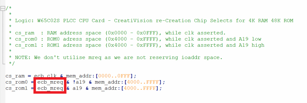
Despite me noting in my source code comments, that I wasn’t using MREQ (because the CreatiVision doesn’t use the IO Bank allocation), I had actually created the ROM “Chip Select” logic by including MREQ, instead of just using the plain CLK high signal (as I had intended).
The result of this, is that with my bank select DIL switch in it’s default all Off switch positions, the IO Bank signal was activating when the top 256 byte bank of memory was being addressed ($FFxx), effectively de-asserting the MREQ signal, and instead asserting IORQ for this top bank of memory.
The top of memory, on a 6502 system (of course), includes the Reset vectors. So, by me inadvertently using MREQ in my ROM chip select logic, the system was failing to read the correct reset vector (explaining the blank screen!).
So, here is my mistake:
And, here is my correction.
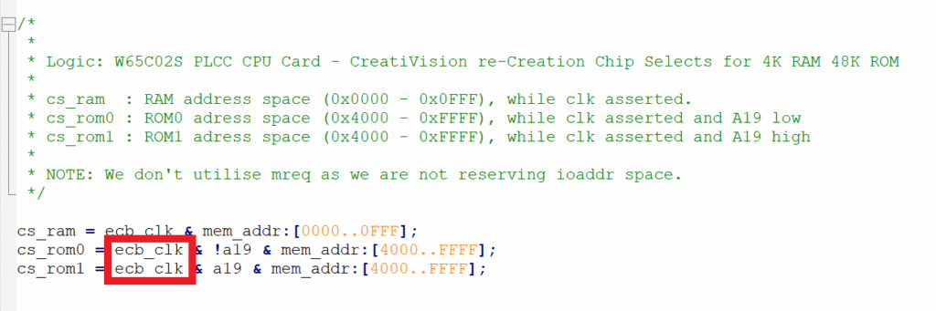
With the PLD source now corrected, and the PLD re-programmed, I was once again ready to try our test, yet again!
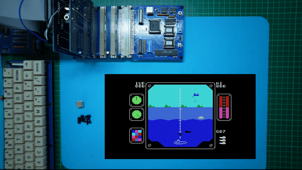
Success
And, I finally have success!
So, I can only offer my apologies for the delay, that this rather stupid PLD code error brought, to me publishing this new post / video.
But, hopefully, by me sharing this experience of my fault-tracing, it will perhaps help you feel better about your own fault-finding journeys.
At the very least, when you do have a fault, know that you are not alone!
Fault-Finding is Fun
It doesn’t matter how many years of experience you might have, silly and time consuming mistakes can still be made!
The key thing, is to know that locating a fault is always just a matter of patience and time.
Fault-finding is, pretty much, just a process of logical testing and logical elimination of each potential issue, and always knowing that you will eventually find the fault.
In my case, I eventually discovered that I’d made an error in my PLD address decode logic, which, in retrospect, is significantly more likely than a faulty chip!
So, now it’s over to you, to decide what you’d like to build with my new favourite 6502 CPU Card. Perhaps it’s also time for you to also build your own CreatiVision re-Creation?
CreatiVision Cartridges “Intro” Graphics
To close this post, for those interested, I’ve included at the end of the linked video, a step-through of the start-up Intro Graphics of the 16 switched ROM cartridges, which are included in the CreatiVision ROM files.
On the video, my new Video Capture card giving you a clean view of the retro-graphics of each of these classic CreatiVision cartridges.
Have fun!