
I’ve always enjoyed playing with OLED display panels, with their sharp clear pixels, and inky blacks. Unlike LCD, where backlight driven displays turn blacks into greys and colours generally just don’t “pop” like they do with an OLED display.
Join me as I present my new OLED Display Card, walk-through the design changes to the final v1.2 release version, and review the source code for my initial testing. Then complete the testing, and talk about my future plans.
Background
This project has also been driven by my early days. My first graphics capable computer, had a relatively low resolution monochrome bit-mapped display.
In those early days, we generally used an old CRT Television, which we fed with either an RF signal through the aerial socket, or we modified the TV for a direct Composite Video input.
I have fond memories of my first “Video display capable” computer, which was the 1979 DREAM 6800, published in the “Electronics Australia” magazine.
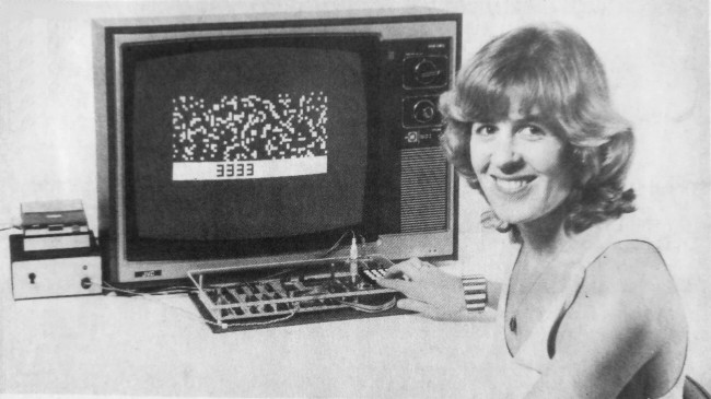
The DREAM 6800 was also my first introduction to a higher-level language. Well, it was higher-level than the machine code that I was using at the time!
The Dream 6800 included a CHIP-8 bytecode interpreter, which was originally implemented on the RCA COSMAC VIP system.
CHIP-8 was a language originally based around a 64 x 32 pixel graphic display, which both the DREAM 6800 and COSMAC VIP computers implemented, via a Video connection to a CRT TV or video display.
With this background in mind, the modern availability of OLED display modules, providing a really nice self-contained, OLED quality, 128 x 64 pixel graphic display, was something we couldn’t even imagine existing back in the late 70’s / early 80’s.
Certainly, back then, it is something we could have only dreamed of getting our hands on!
OLED Panel Choice
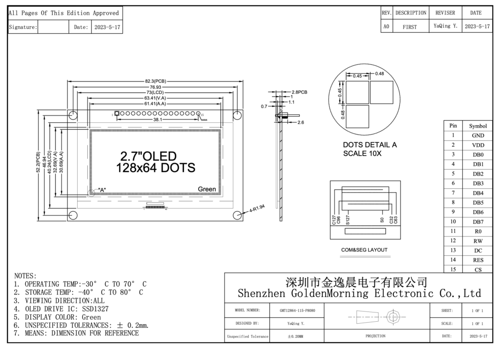
So, given our MECB standard board size, I’ve chosen a really nice 2.7″ 128 x 64 OLED display panel, which fits nicely onto a MECB Card.
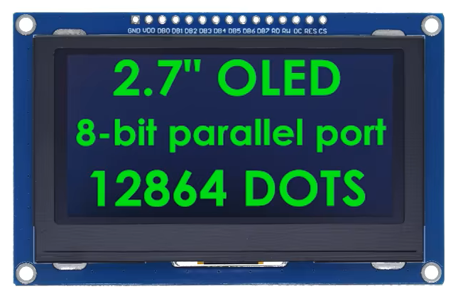
I’ve also chosen to use a green version of the OLED display, which nicely replicates the early “green screen” monochrome computer monitors. These were popular for reducing the eyestrain originally caused by staring at white phosphor TV screen images for too long.
This makes an all-in-one 128 x 64 graphics OLED display Card, for our experiments and retro re-creations.
Potential
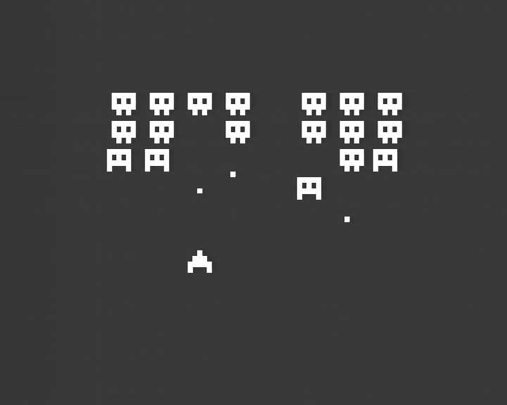
Its has also definitely occurred to me, that this display card could even be used to create a self-contained CHIP-8 based system, in either the original 64 x 32 resolution, or as a high-resolution 128 x 64 CHIP-8 re-creation.
Of course, it could also be used as a self-contained integrated display, for displaying anything you like!
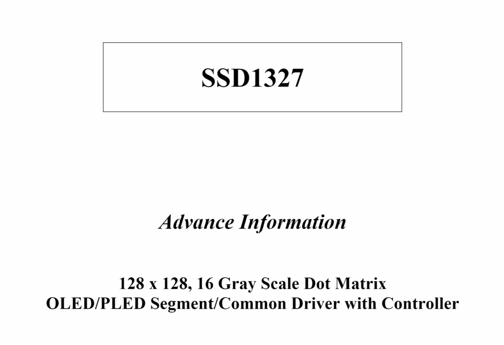
The SSD1327 that the Display module uses also allows 16 shades of grey (4 bits per pixel), so you’re not just limited to On & Off pixels.
Implementation
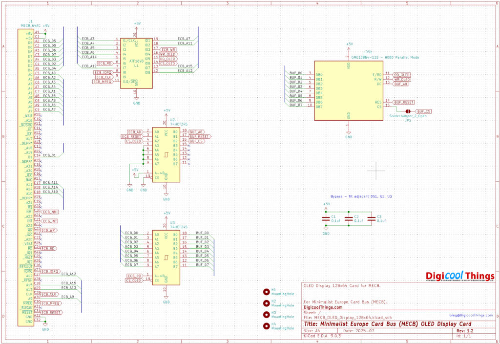
So here’s the final v1.2 schematic for my MECB OLED Display 128×64 Card:
To work with our 8-bit retro systems, these OLED Display Modules are available with an 8-bit interface.
First Release is v1.2?
Now, I should explain how I got to v1.2 already.
Unfortunately these display modules don’t come with a detailed data sheet or schematic.
You only basically know the driver IC the module uses.
As mentioned before, this module uses a SSD1327 controller, which the controller’s data sheet notes is a 3.3V logic level device.
The referenced OLED panel connections are also labeled with VDD for the power connection, therefore powering the panel with 3.3V power was my assumption.
My initial v1.0 failure
So, in my usual over-confident way, given that this was a relatively simple interface design, I dived straight into designing a v1.0 prototype PCB.
This was based on a circuit using a retro friendly (Through Hole), 3.3V regulator and 3.3V level shifters, for interfacing to our 5V TTL level bus.
And… it didn’t work!
Since, I’m always getting taught another lesson, let’s just say that this is a good reminder that sometimes it just makes sense to breadboard your new circuit ideas first.
Moving on to v1.1
With some googling, I finally found the a schematic for the OLED panel. Found on the original manufacturers website.
Here it is:
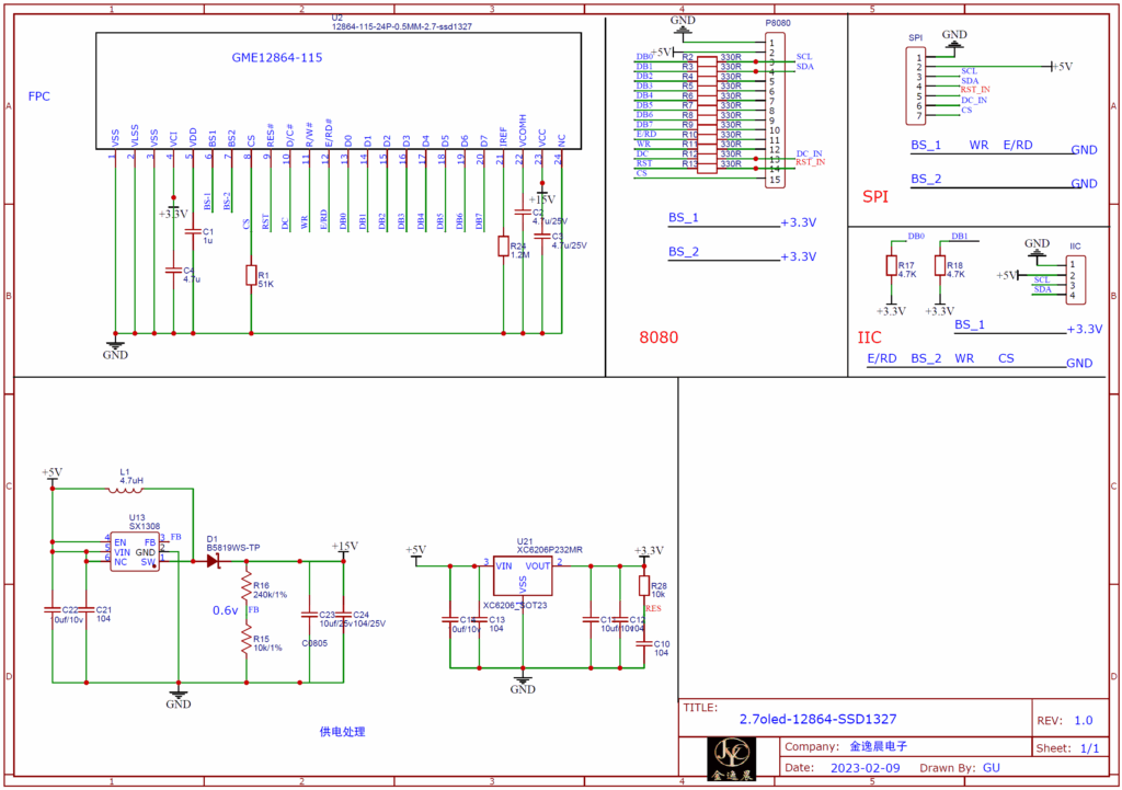
As you can see, there are a couple of key things to note:
Firstly, the module is in fact 5V powered, with onboard regulators for the 3.3V (and other), power needs.
I should have noticed this, but I actually designed the PCB before I even received the OLED modules.
Secondly, you’ll notice that the 3.3V logic level interface / translation is implemented via a simple series resistor interface.
This is probably okay for interfacing to a regular 5V TTL logic level I/O port, but definately not ideal for directly connecting to our bus.
So, we do still need to include some buffers to appropriately interface to our bus.
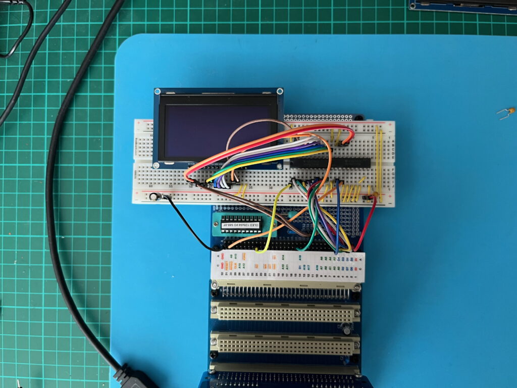
So, it was time to break-out a breadboard and an MECB Prototype Card, to properly test the design.
Which is, of course, what I should have done in the first place!
And here’s a photo of my properly done breadboard test:
Finally happy to release at v1.2
Despite this now working perfectly, and having designed and ordered my new v1.1 PCBs, I then decided on one further design change (to satisfy my perfectionist tendencies).
This was because I had logically used TTL 74245 bidirectional buffers for the data bus, and 74244 octal buffers for the address and control signals.
These are the typical TTL bus buffer chips, that we’ve always used, for interfacing our 8-bit microprocessors.
But, after completing my v1.1 design, I noticed that the 245 bidirectional buffer chips are now much cheaper these days, than the 244 uni-directional octal buffers.
So, as I thought it was more “maker friendly” to just use two 74HCT245 bidirectional buffer chips, instead of two different chips, I redesigned yet again, for v1.2
So, here we are, at the third and final version of this seemingly simple project!
So, here is the final v1.2 schematic:
You can also see that, in addition to the standard glue-logic PLD, we have used two 74HCT245 bus buffers to isolate the OLED panel’s in-built series resistor 3.3V logic level translation, from our 5V TTL level MECB bus.
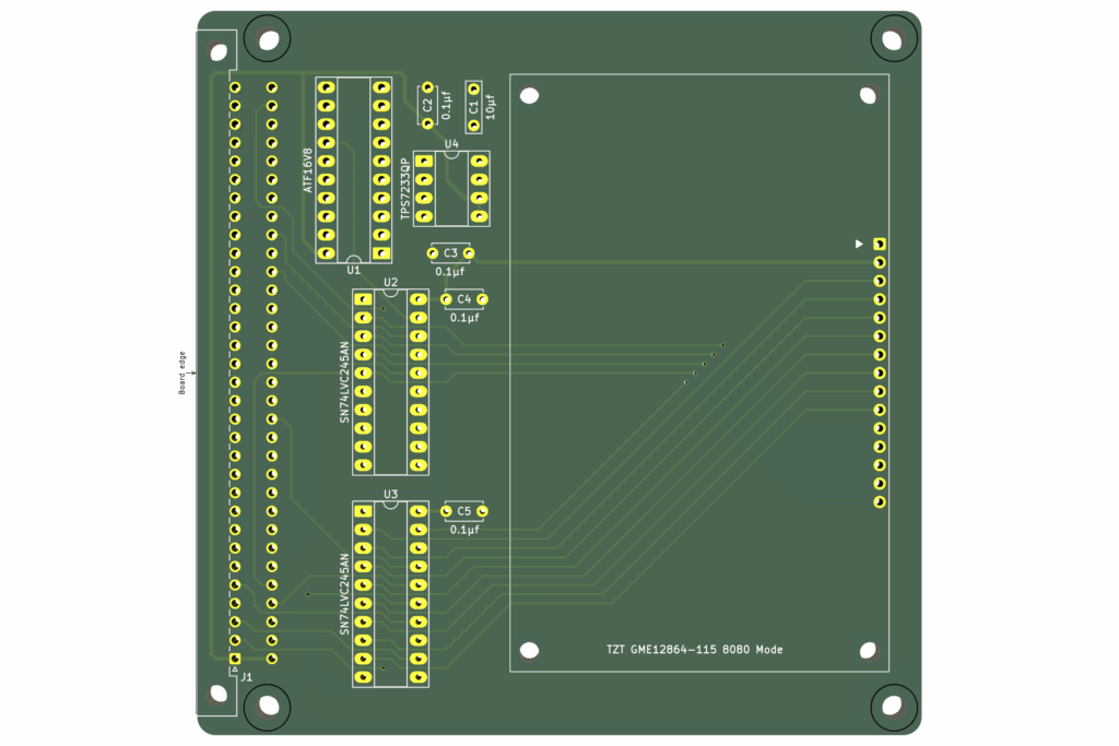
So, here is the PCB 3D render of our final routed v1.2 PCB:
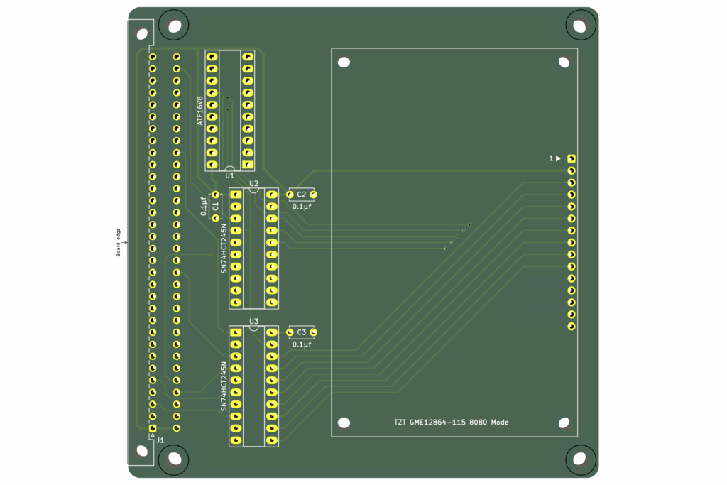
As you can see, the OLED module fit’s nicely on the standard MECB Card size.
I’ve used a PCB header and provided holes for PCB stand-offs, to enable mounting the display directly onto the MECB Card.
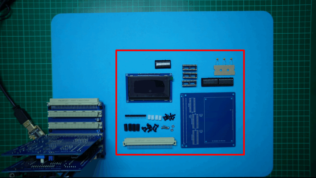
First Card Assembly
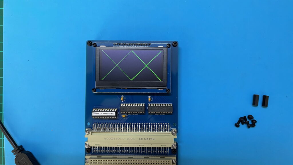
So, on my workbench you can see the first manufactured v1.2 PCB, and all of the components needed to fully assemble the Display Card:
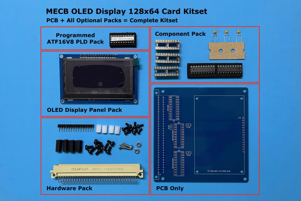
On my Tindie Store, I’ve made available the PCB and some Optional Packs, which together provide all of the parts to make a full Kitset.
So, next I get the first v1.2 Card assembled. Be sure to watch the linked Video above, if you’re interested in my assembly steps.
Once I’ve fully soldered the PCB, I next get the OLED module plugged in, and nicely mounted with it’s PCB stand-offs.
Note, that the display panel uses M2.5 stand-offs. These are supplied in the Hardware Pack as white stand-offs, to easily differentiate them from the usual black MECB Card M3 stand-offs.
Okay, with the OLED panel mounted, I then fit the two DIL IC’s that provide the bus buffering (the two SN74HCT245N’s).
Finally, we have the ATF16V8 PLD for our address decoding.
I’ve chosen to locate the OLED Display Card at I/O address block $88 – $8F, being just above the $80 – $87 that I’d previously allocated to my existing VDP Display Cards.
These different display cards can therefore happily co-exist in an MECB system.
Here’s the PLD address decode logic:
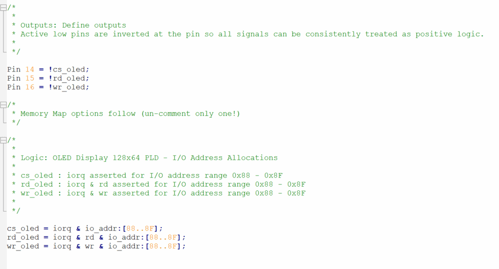
As you can see from the PLD source code, I’ve used all three allocated outputs of our MECB standard ATF16V8 PLD configuration.
Two are used for independent Read or Write OLED panel signals (rd_oled and wr_oled).
While the third output (cs_oled), is used for a general OLED panel select for enabling the 74245 buffers.
So, Next I get the programmed PLD inserted.
And, we are now ready to give our newly assembled OLED Display Card its first test.
Time for Testing!
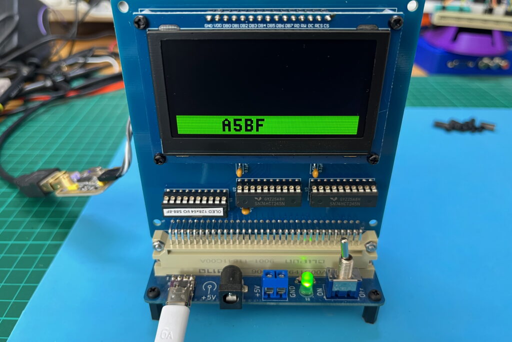
For the purpose of showing the card in operation on my video, I insert it into the horizontal backplane connector, so it’s in clear view of my overhead camera (be sure to watch the linked Video to view the testing).
Later, I will locate the OLED DIsplay Card in the front vertical socket of my backplane’s bus connectors, to make it a nice built-in MECB system display.
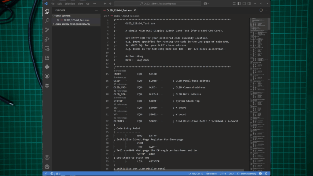
For the initial test, I’ve written some 6809 code to initialise the display panel, and display some simple diagonal lines.
All we need to know (at this stage), is that our display is working correctly and we can control it on our retro 8-bit MECB system bus!
So, let’s take a quick look at the code (watch the linked Video for a code walk-through).
Next, I assemble and transfer across the assembled code, and then run it (from ASSIST09), with C 0100
All looking great, with our simple, full resolution and half-resolution diagonal lines test!
What next?
So, now that we are up and running and we have some initial 6809 Assembly drivers for our display card, I’m feeling the urge to re-live some retro nostalgia and have some fun.
But, for now I’ll just leave you with a clue to what I’m now working on re-creating.
More to come.