
A viewer (@CYAN), asked about the variable speed controller, in my recent KOTTO Fume Extractor video. See my earlier post / video here: https://digicoolthings.com/my-fume-extractor-upgrade-hakko-to-kotto/
So, not being someone who ever needs an excuse to pull something apart, I thought I’d take a closer look than what my earlier review revealed.
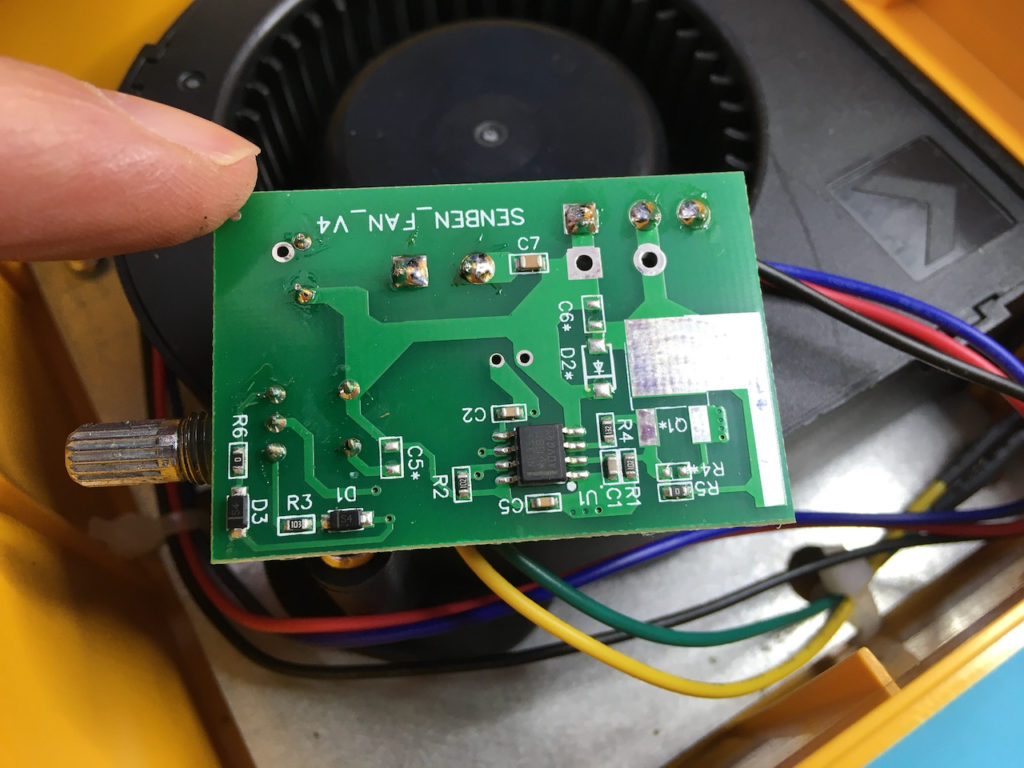
I was pleasantly surprised to find that it wasn’t just a low value potentiometer dropping the voltage to the fan motor. There is in fact a nice little NE555 timer based speed controller running the show. 🙂
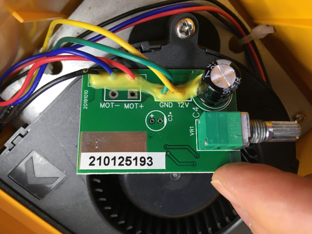
The 555 itself is controlled by a 100K (B104) switched potentiometer (VR1).
No need to reverse engineer this circuit, but it can be seen that the circuit board also has space for some additional components, including a transistor (Q1), presumably to allow for driving a higher current motor.
My only concern is that the apparent Back EMF protection diode (D2) is one of the missing components! Perhaps this is something that would be fun to take a look at on the scope, just to see if we are getting any back EMF surges going back into the 555. But, at least for now, I’m aware of this potential issue if my fume extractor ever stops working.
In any case, I’m more than happy with my KOTTO Strong Suction Hose Fume Extractor, which has been happily keeping all soldering fumes well away from my nose.
For your viewing pleasure, here’s the bottom and top photos of the controller PCB.
Hey man! I created an account to say thanks for hearing out my request.
Apparently I’m using the same application on my project but with a better IC? (LMC555). I’ve heard that NE555 IC are not efficient because of its high current draw, current leakages, and higher voltage rail headroom. I don’t actually fully understand all this stuffs and why they are not good signs since I’m still new to electronics engineering but so far the project I did has been working great so far, I only need the hose and the enclosure and It’s good to go. (I can make a video for the speed controller)
But still I’m thinking if I could use a better components, namely a microcontroller or an op amps with schmitt trigger? Still don’t know how to apply all these things tho.
Hi Cyan. Awesome to hear you are diving into making a DIY solution.
I believe, for this application, a 555 timer is actually a very good choice. Just for controlling fan speed, although a microcontroller could certainly do the job, it would be seriously overkill.
Note that the LMC555 is a modern CMOS version of the original 555 timer IC. Being implemented in CMOS does provide significantly lower power drain and also a higher operating speed capability. However, this doesn’t necessarily mean it’s a better IC. It depends on the application!
On the downside, the CMOS version is not able to source / sink the same high output pin currents.
eg. The LMC555 can typically source only 10ma and sink 100ma, at 12V supply.
In comparison, the NE555 can both sink & source 200ma.
Depending on what you are directly driving with the output pin, this may be a significant issue for the CMOS version. Of course, if your design is using a driver transistor (or MOSFET), then this shouldn’t be an issue.
Both are good for 12V operation. The NE555 has an Absolute Max Vcc of 16V, whereas the LMC555 has Absolute Max Vs of 15V (noting of course that you should never run any IC at its Absolute Max rating).
Also, depending on the application, the 1mA – 10mA typical supply current of the NE555 (versus 150uA for the LMC555), may not actually be significant, in the scheme of things, if your project is also driving a higher power device (like a fan!).
Hope this helps out with your design ideas. have fun! 🙂
Good day sir!
After months I’m finally back to this project again, but I noticed a problem with mine. When I crank the potentiometer all the way to the right it goes to its max speed (as it should be), but when I crank all the way to the left it goes to its max speed again. This doesn’t happen when I don’t spin all the way to the left.
Can you tell me what’s happening? I replicated almost all of the components here except for the capacitors.
Thanks a lot!
Hi again. Concerned when you say: “… except for the capacitors”. You will need at least 1 capacitor in your circuit for the timing, and you should probably also have a power bypass capacitor to smooth the power to the 555!
As I noted, I didn’t reverse engineer the circuit, however it is clearly a common PWM 555 design, based on the variable resistor with 2 diodes which are used to control varying the capacitor charge / discharge rates.
I’d suspect the issue you have may perhaps be related to the actual component values you’ve chosen. Have you researched example 555 PWM circuits for motor speed control, via google, to give you some ideas?
I’d also be sure to include a flyback diode across your motor (eg. a 1N400x). This appears to be missing from the Kotto PCB. As a motor is an inductive load, it will generate reverse bias voltage spikes when being switched on and off (by the PWM signal). This will potentially play havoc with the 555 timer’s normally expected operation, and worst case could certainly damage the device.
Hope this helps.
Thanks for the quick reply,
I forgot to mention that I have the capacitors but with a different value to achieve a 25kHz frequency on the output pin, but it seems that different combinations to achieve this doesn’t fix the problem (the one I mentioned in my last reply). And yes I did google about the 555 before diving into this.
Perhaps I have a defective fan. I might try to buy another one to check if this is the case.
I also forgot to mention that I have a 4 wire fan, with dedicated PWM wire, connected to pin 3 of 555 IC.
Another problem was output frequency of 555 IC seems to be changing depending on the potentiometer. Isn’t this supposed to be fixed? I don’t have an oscilloscope to check this one, so I used my DMM.
Thanks a lot!
Cyan
I would suspect that if driving the PWM wire of a 4 wire fan, then the appropriate frequency and PWM duty cycle range would be dependant on the specifications of the PWM fan.
I haven’t tried driving a PWM fan myself, so I can’t really offer much advice here.
Perhaps you could try using the 555 PWM circuit to directly drive the fan motor (via a transistor or mosfet), to at least rule-out the fan’s inbuilt PWM wire control as being an issue with your circuit?
Just a thought that might help to isolate the problem, if you’ve no access to an oscilloscope to see exactly what’s going on with your PWM output.