
Continuing on my Hexadecimal Keypad design journey, which started with a series of 3 videos published a couple of years ago.
For this part 4, I present my 4×5 matrix Cherry MX Keyswitch based Keypad version, inspired by a retro re-creation project that I’m currently working on.
Introduction
Around 2 years ago, I published a series of 3 videos, covering my Hex Keypad design journey.
The full Hexadecimal Keypad Playlist can be found here.
These videos started with my initial Tactile Switch based Hex Keypad design.
The last video then covered the 2 year evolution to finally arrive at my Ultimate Cherry MX keyswitch version.
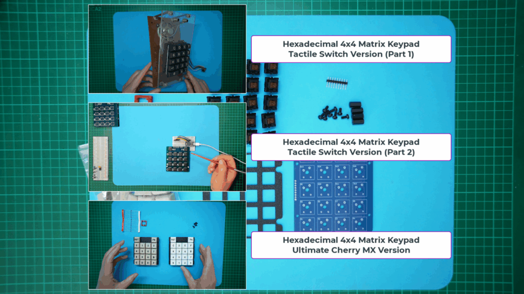
So, now, a further 2 years later, I’m introducing another version.
The original Keypad was a 4×4 matrix with 2 additional non-matrix keyswitches, normally used for a Reset button and a Function key.
A new 4×5 Matrix Hex Keypad
A retro computer re-creation project (which I’m currently working on), really wanted an extended 4×5 matrix Keypad design.
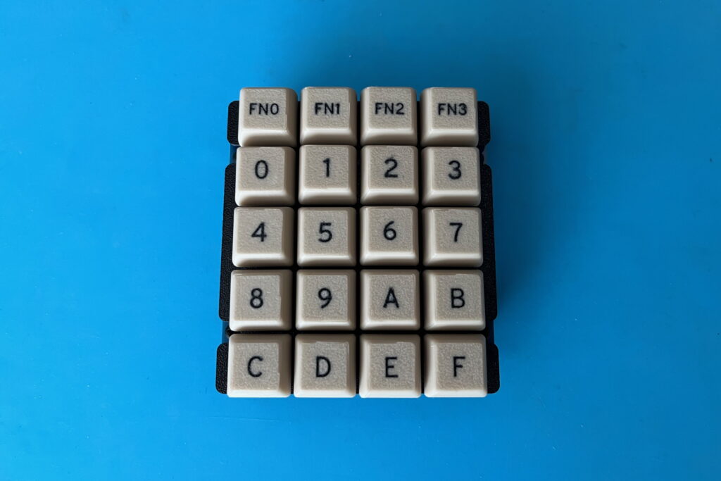
This is to allow for the usual 4×4 matrix for the 0 - F Hexadecimal Keys, but in addition, adding a fifth row to the matrix for implementing 4 Function keys.
Essentially the new design is a simple 4×5 matrix, instead of the existing 4×4 matrix +2 separate keyswitches design.
Which version will best suit your own Hex Keypad based project, depends on how you wish to utilise the extra Function keys.
So, since I’ve now designed my new 4×5 matrix version, I thought I may as well also offer it to other enthusiasts, as an alternative to the existing Keypad.
As a result, you will now find both of the Cherry MX Hex Keypad versions on my Tindie store, so you can choose which one you prefer.

For this post / video, I’ll avoid replicating all the design details, including describing the optional diode use, and also demonstrating installing these optional Keyswitch diodes. This was all covered in the last Ultimate Cherry MX Keypad video.
For the full background story, please first view the prior video.
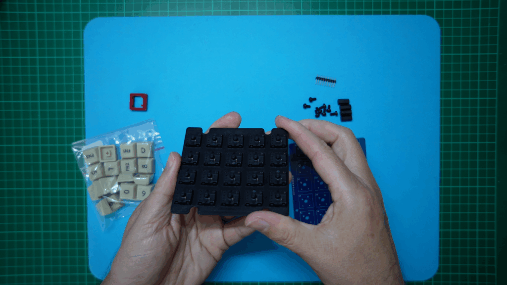
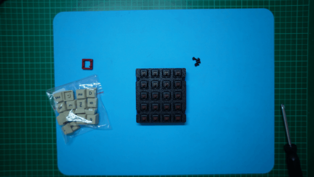
So, here is what the new Hex Keypad 4×5 Matrix Ultimate Cherry MX Keypad kitset of parts looks like.

In addition, here is the 4×5 Matrix Keypad schematic, which also provides the 9-pin PCB header pin-out:

The prior video also covered the details of assembly, so I’ll just do a re-cap here.
Assembly (re-cap)
For assembly, I first solder on the 9-pin header, which is inserted from the underside of the PCB.
Then, optionally, if you’re not using the diodes, I solder-bridge the 20 PCB jumpers, to bypass the unused diode pins.
With the solder-bridges now done, this is what it looks like.

Then I assemble the 20 Cherry MX keyswitches onto the 3D printed switch mounting plate. Noting that the switches are pressed into place from the top side.
With all the switches fully inserted into the mounting plate, the next step is to check that all of the keyswitch pins are straight.
Make sure none of the keyswitch pins are bent, either from shipping, or perhaps bent with your fingers while inserting the switches into the mounting plate.
With all the keyswitch pins straight, the PCB should now just drop into place.
We’re now ready to solder all the keyswitches to the PCB. While doing this, be sure to use downward pressure on the assembly on your soldering bench, to ensure each switch is soldered flush to the PCB.
With that complete, I then screw in the 4 nylon stand-offs, to support the Keypad on my desktop.
Now I just need to pop-on the keycaps and our 4×5 Matrix Keypad is finished.
And, here is the finished Keypad!
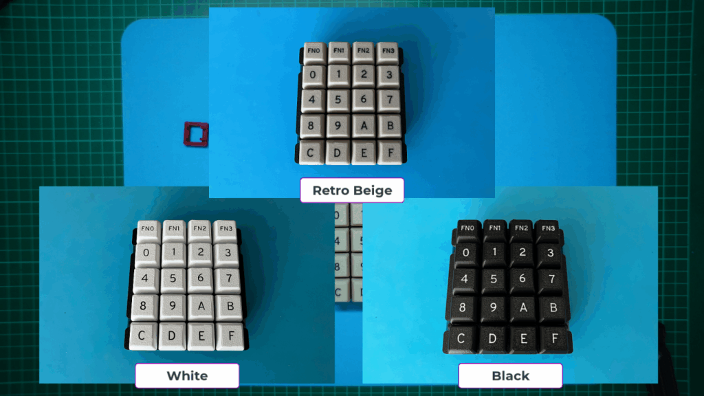
Keycap Colour Choice
Note that I’m currently using the “Retro Beige” coloured keycaps, but I also make these keycaps in White, with black legends, and also in Black, with white legends.
Here’s what they look like.
Okay, now I should get back to working on the project that inspired this new 4×5 matrix version of my Hex Keypad.
If you’d like to follow along, or you have your own project that would benefit from a nice Cherry MX keyswitch based Hex Keypad, then be sure to visit my Tindie store.
Have fun!