
It’s now time to fire-up and hands-on explore, the early retro 8-bit microprocessor user experience, which is provided by my DREAM 6800 (now 6809) re-Creation.
My DREAM 6800 re-Creation, is upgraded to a 6809 and higher resolution graphics, but is still keeping true to the original 1979 experience of one of the first stand-alone video graphics based microprocessor systems.
Based around my new Keypad Interface + Sound and Tape Interface module, designed for your early retro microprocessor creations.
Part 1 Recap
In the previous blog post / video (Part 1), I covered the background history of the original 1979 published DREAM 6800, which inspired my 6809 based DREAM re-Creation project.
I then covered the design of my Keypad / Sound / Tape Interface module, which I created to provide the I/O for my DREAM re-Creation.
Noting also, that the interface module could also form the basis of any other early retro project, which requires a Hex keypad and a Tape interface.
Next, I went through the interface board assembly sequence, that I used. Then, I demonstrated testing, and also the alignment of this new interface board.
Finally, teaming it up with my existing Hex Keypad 4×5 Matrix and some custom Function Key keycaps, to create an all-in-one Keypad / Sound / Tape Interface module.
This finished module was then plugged into the PIA port of my MECB Motorola I/O card.
Together with my MECB OLED Display 128×64 card, and my 6809 CPU Card, we were then all ready to fire-up my new DREAM 6809 based re-Creation.
So, now that I have it all assembled on my desktop, together with plugging in a good old-fashioned portable Tape deck, and also setting-up a camera to capture the display (that I’m looking at), we’re ready to power-up.
Part 2 Agenda
So, for this Part 2, I’ll go through the use of the system. Covering the CHIPOS operating system, and also the CHIP-8 Interpreter that it includes.
Then, we can take a look at my 6809 based original CHIPOS code conversion, that drives the re-Creation.
After this, we can look at the process of entering and running CHIP-8 programs.
In addition, the process of Saving (Dumping), and Loading these entered programs from tape.
Finally, we’ll take a look at the 6809 conversion of the original DREAM Invaders 6800 machine code game, which was originally written by the DREAM 6800 creator Michael.J.Bauer.
I have faithfully converted the original DREAM Invaders game to now run on my 6809 and OLED display based DREAM 6809 re-Creation.
So, we’ll probably finish-up with a quick game of DREAM Invaders09.
Introduction
Hopefully, this Part 2 will give you a good overview of what it was like back in 1979, when many of us had our first hands-on microprocessor experience, via the DREAM 6800.
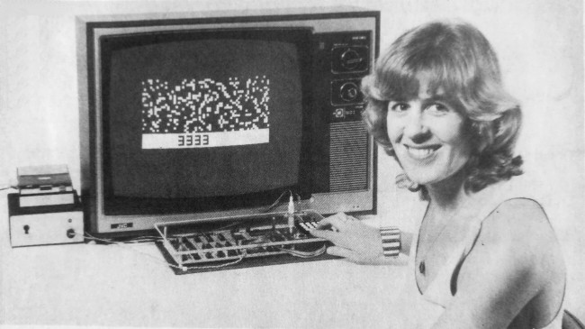
This re-Creation allows you to faithfully re-live the early days experience, of using a stand-alone 8-bit microprocessor system, with a Hexadecimal keypad, chunky graphics, and a Tape interface for saving your creations.
If you’re too young for this nostalgia, then this re-Creation also provides a very realistic experience, if you want to know what it was like in the early home computing days. A time when the use of early hardware, like this, was limited only by your imagination and your creativity.
So, let’s start by applying power!
A Note on Filming OLED Displays
Just before applying power, I’ll also point out that trying to film an OLED display with a video camera requires some compromise.
I needed to set the exposure on the video camera to try and minimise the image flicker that the camera was capturing, whilst also minimising the persistence created by a longer exposure.
Please just be aware that first-hand, to the human eye, there is absolutely no visible flicker and the digital OLED display looks awesomely sharp, rock solid and pixel perfect.
Okay, with that understood, let’s power-up.
Powering Up!
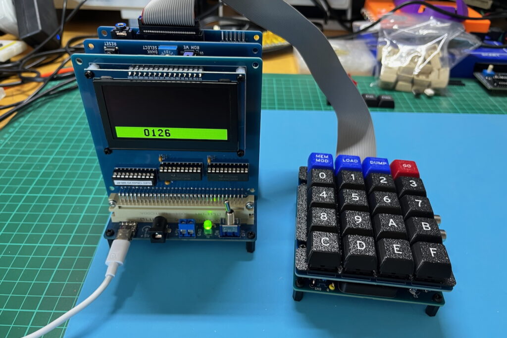
You’ll note the power-up display of the DREAM is quite simplistic.
It simply displays a 64K address, in hexadecimal, which is stored in an internal address buffer.
Now, one first-hand observation is that the display actually looks better than it did in 1979.
Firstly, we have a nice sharp digital OLED display. But also, when powering-up our 6809 based re-Creation, I have defaulted the display mode to use the new higher resolution 128×64 display mode, together with the new higher resolution 6×10 font.
The original DREAM 6800 had only a 64×32 chunky graphics display, and used a very basic and chunky 3×5 pixel font.
We’ll change to that lower resolution mode in a little while, so you’ll see what it was like.
Displaying / Modifying Memory
Okay, so entering a sequence of 4 hex digits will replace the currently displayed address with a new address.
Note that each key entry is accompanied with a audible bleep for feedback.
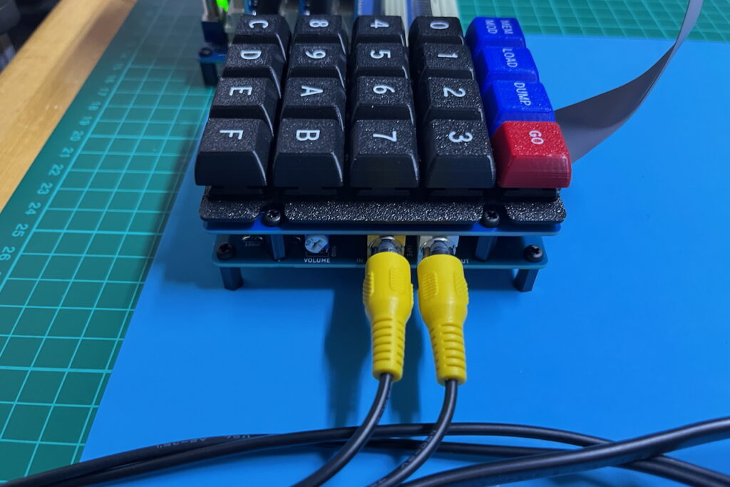
I’ve adjusted the sound volume via the VOLUME trimpot, which is on the interface module just below the Keypad, to the right. So, it can range from very loud, to barely audible, to suit your preference.
Along the top of the Keypad we have the four function keys.
As labelled, the first function enters memory modify MEM MOD mode.
Pressing MEM MOD displays the byte that’s located at the displayed address.
You then either enter the 2 hex characters of a byte (which you want to replace the displayed byte with), or, you press the MEM MOD key once again to skip to the next address.
You can also press any of the other Function keys to exit the MEM MOD mode, returning to just the address display, once again.
If you enter 2 hex characters, to update the byte at the indicated address, the new byte is stored, and the address auto-increments to the next address.
In this way, you’re able to directly type-in a sequence of bytes to fill a sequence of locations in memory.
A few Key Memory Locations
Okay, so with this understood, there are a few key locations in memory, that you’ll want to know, to get started.
Firstly, there are locations 0002 and 0003, and also 0004 and 0005
These four consecutive memory locations hold the Start address and the End address (+1) for Tape Load and Dump operations.
It was generally the common practice to round-up the memory range being loaded or dumped, to the nearest 256 bytes.
So, for example, a small program located from memory address 0200, might (for simplicity), specify a Load or Dump address range of 0200 - 0300
Speaking of which, 0200 is the typical start location for user programs.
It’s also the start location for any CHIP-8 programs executed by the internal CHIP-8 interpreter.
The internal CHIP-8 interpreter is located from ROM address C800
So, to run a CHIP-8 program you would enter it, or load it, starting from address 0200
If entering it you could then also save it to Tape. That is, Dump it to Tape.
So, this covers the Load and Dump function keys.
Running Your Programs
Then when you are ready to run your CHIP-8 program, you run the CHIP-8 interpreter at address C800
Likewise, if you were Loading, or entering a hand assembled machine code program, you’d enter the address that you wanted to execute it from.
Then, with the required run address entered and displayed, you just press the GO function key, to jump to the displayed address.
After running a program, via the GO key, you can return control to CHIPOS once again, by pressing your system Reset button (in this case, located on my CPU card).
Another Memory Location to Know About
Now, the other memory location you may also like to know about, is 001C
001C holds the new OLEDRES value, which is 01 for the 128×64 high-res mode, and 02 for the original 64×32 chunky graphics mode.
So, if I now enter 001C and press MEM MOD we will see that the current boot value is 01
If I now key in 02 you’ll note we are now in the original 64×32 graphics mode.
Straight away, you can see on the display, that the font has changed to the original ultra chunky 3×5 pixel font.
The displayed font provides a simple indication of which display mode we are currently in.
So, now lets take a quick look at the CHIP-8 language.
CHIP-8 Language
CHIP-8 provides a simple, yet powerful, byte language that provides all that you need for creating chunky graphics games.
Each CHIP-8 command is two bytes long (so, four Hex characters).
There are around 32 CHIP-8 commands, all summarised in this table reproduced from the first Electronics Australia article in 1979, for the original DREAM 6800.
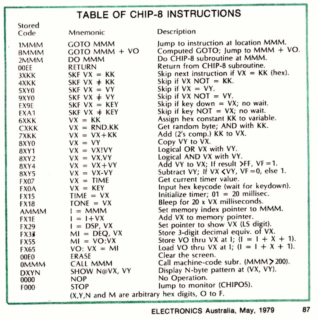
You may notice that there are 33 commands listed. That is because the STOP command F000 is not actually a command at all.
When the CHIP-8 interpreter hits an invalid CHIP-8 command it simply exits back to CHIPOS.
Hence, you can consistently just use F000 as a non-valid CHIP-8 command to exit the interpreter back to CHIPOS.
I’ll let you read through the CHIP-8 commands to get a feel for what’s available.
But basically, you have 16 byte sized variables, 0 through F of which F is a special flag variable, that is used (for example), to detect pixel overlap collisions for your gaming applications. Variable F is also used to indicate arithmetic overflow.
In addition you have a 12 bit address pointer I
You can even expand the number of Variables by swapping-out variables to memory using the memory pointer.
The address pointer is 12 bits, as CHIP-8 is limited to 4K of memory space.
But, with CHIP-8 you can do a lot in just 4K. Not to mention, you probably don’t want to key in any more than a 4K program, as that’s over 8000 hex characters!
But, this was how we created programs in 1979.
In addition, if we wanted to write a machine language program, or a machine language subroutine for our CHIP-8 program, we’d have to “hand assemble” it. Learning all of the microprocessor hex op-codes of-by-heart!
Those were indeed the days!
As I said earlier, this DREAM re-Creation allows you to realistically experience (or re-experience), just what we had, and did, back in the early microprocessor days of the late 1970’s.
One New CHIP-8 Command (for my DREAM 6809)
Now, to round out this quick CHIP-8 introduction, I’ll mention that I have added one new CHIP-8 command.
It is FX95 Which enables us to very easily change the OLED display resolution from within a CHIP-8 program.
Simply replace the X with either 1 for the power-on default 128×64 resolution, or 2 for the original 64×32 resolution.
CHIPOS 6809 Conversion
So, with CHIP-8 introduced, I’ll now take a quick look at the CHIPOS 6809 conversion source code, for my 6809 re-Creation.
Here is my commented header of the CHIPOS6809 assembly source, where I give a brief overview of the changes that I’ve made.
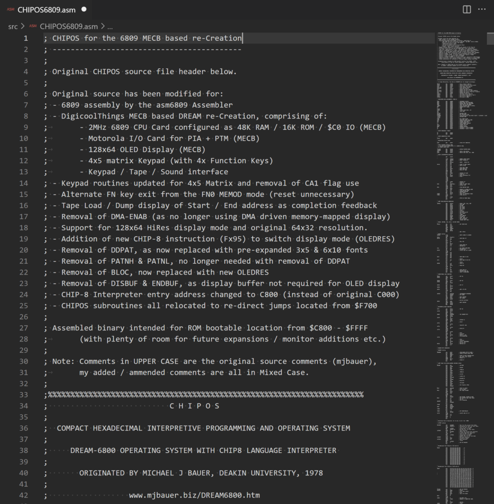
First, is a summary of the hardware that this is designed to run on.
Then, the removal of the PIA’s CA1 trigger for a Keypad key press, required a re-work of the keypad scanning code. As did the implementation of a 5th matrix row for 4 new function keys!
Also, I utilised the new added function keys to enable a new way of exiting the “Memory Modify” MEM MOD mode. This is via the press of any other function key, as opposed to the original requirement to use the system Reset.
In addition I changed the user notification of Tape Dump & Load progress (start & end of Dump / Load), to display the start address, and then display the end address on completion.
On the original DREAM 6800, tape Dump / Load progress was signaled by turning-off the display (disabling DMA), during tape operations.
This was required for timing reasons. Whereas, with our new OLED display, no DMA microprocessor interruption is necessary, so we can use this tidier method for Dump / Load completion notification.
Next, the entire memory mapped graphic display was replaced with drivers for the OLED panel display.
A small note here is that the use of a parallel 8-bit display panel was critical, as only the parallel interfaced panels allowed the reading of the internal display buffer contents. Serial attached panels only allow the writing of display data, therefore would require an external memory buffer to be maintained, as CHIP-8 implements an Exclusive-Or (XOR) pixel display function.
In addition, I implemented a new higher resolution font alternative, to take advantage of the new ‘Hi-Res’ 128×64 display mode. Effectively adding a smoother 6×10 font to the existing chunky 3×5 font.
It’s worth also noting here, that Mike (the original DREAM 6800 designer), was originally limited to the 1K ROM space of the original 2708 EPROM which held his CHIPOS operating system.
Therefore, Mike was forced to improvise to get the full code to fit in the 1024 bytes available.
He had to get creative and also accept a few limitations, in order for the code to fit within the available 1K ROM space.
One aspect of this creativity was that Mike implemented a compressed font, which in combination with an efficient decompress routine, saved on ROM space. I no longer needed this type of ROM space saving, so I instead went for a more straight-forward simple font image table.
Fortunately, the 1K ROM space limitation is now a thing of the past, and we can be more focussed on function instead of available space!
To support both 64×32 or 128×64 display modes from within a CHIP-8 program, I added an additional CHIP-8 instruction, that allows setting the display mode (either the original 64×32 or the higher resolution 128×64).
As you’ll note from the header comments, I also changed the original C000 CHIP-8 interpreter address, to now be C800
For CHIP-8, C800 seemed more intuitive to me.
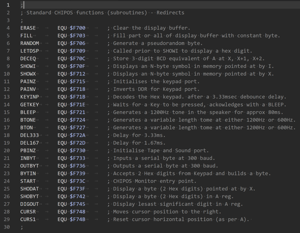
CHIPOS Subroutines Re-direct Table
Next, the originally published CHIPOS subroutines have all been relocated to a fixed address re-direct table, starting from $F700.
In addition, there was the removal and refactoring of features no longer necessary.
Apart from all this, a number of smaller changes were made along the way, related to the new 6809 based hardware.
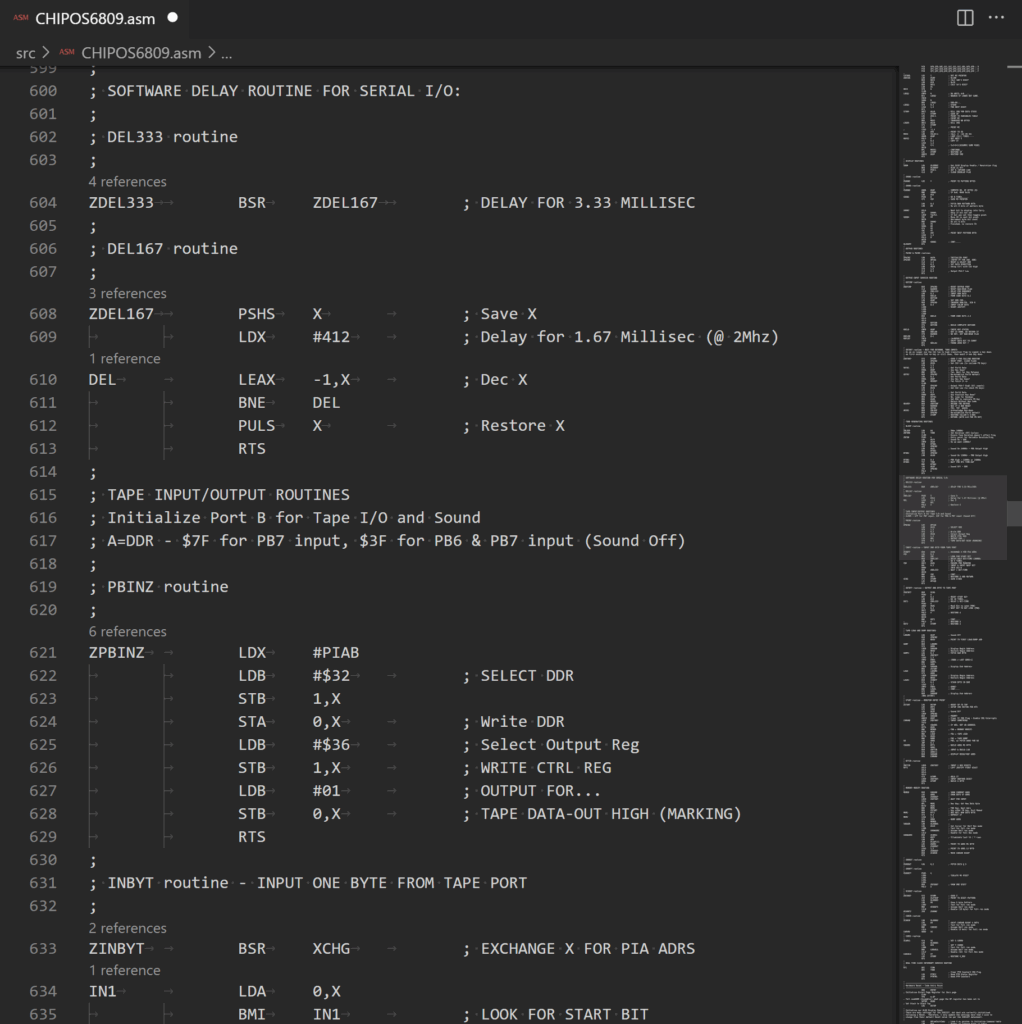
Source File Comments
Finally, I’ve noted in the header that the Source file comments which are in UPPER CASE, are the original source comments by Michael Bauer. My added code comments, or comments for my amended code, are all in Mixed Case.
Here’s an example of this around the Delay routine. Where original code and comments are in UPPER CASE, but my amendments are commented in Mixed Case.
Entering & Running our first CHIP-8 Program
So, with that all explained, I’m going to start by keying in the first example CHIP-8 program, that appeared in the second Electronics Australia article.
Here it is.
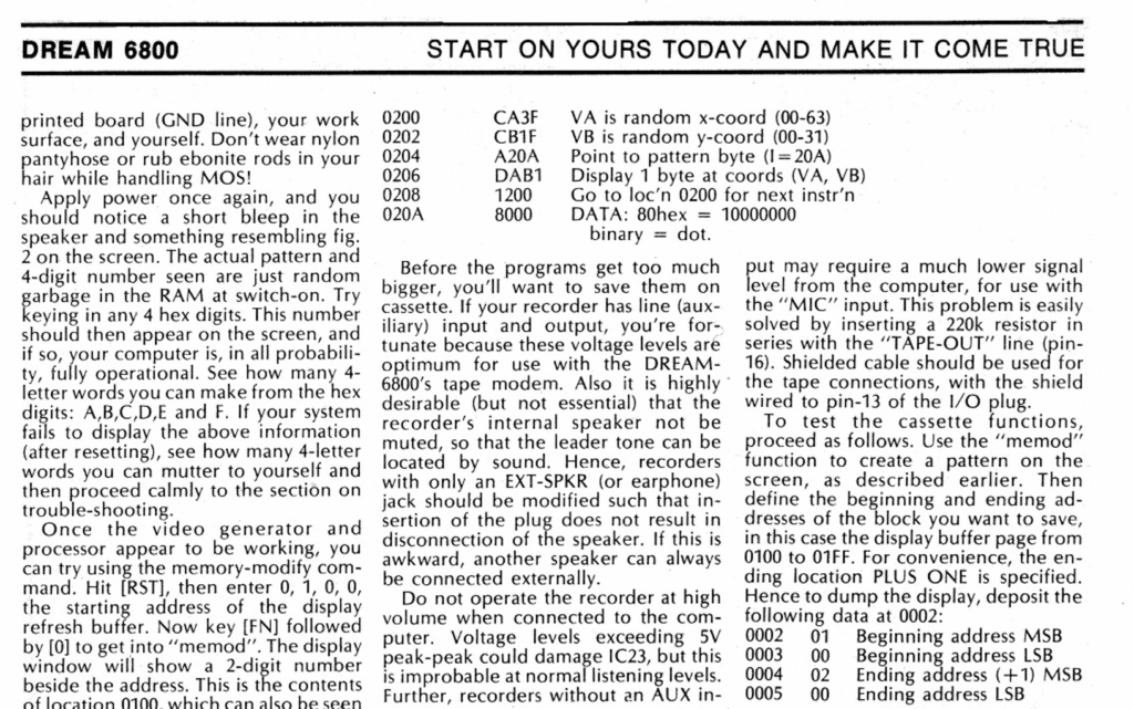
This was a simple short program to display random dots on the display.
This achieved a few of things.
Firstly, it demonstrates how simple and capable a short CHIP-8 program can be.
Secondly, it demonstrates the exclusive-or (XOR) functionality built into CHIP-8 graphics display (that is, a dot drawn on top of an existing dot, erases it).
Finally, it also demonstrates the pseudo-random sequence of the random number generator (all dots will eventually be drawn, then erased, due to the pixel Exclusive-Or function).
So, noting we are still currently in the original 64×32 mode, I’ll get that short program keyed in, starting from address 0200
With the program keyed-in, we can now run it by entering address C800 (for the CHIP-8 interpreter), and pressing GO
There we have it. Our first CHIP-8 program entered and running!
Please what the linked Video (above), to see this in action.
Re-Living the 1979 “First Program” Experience
You may (or may not), be able to imagine just how that felt back in 1979, as our first program running experience, back in the days when we didn’t have computers (or the internet)!
It may be difficult for younger folk to comprehend this, but for those of us who experienced it first-hand, back in 1979, it was a truly magical and a future life defining experience!
Using the Tape Interface
Okay, with that done, let’s try the Tape interface.
One thing about keying in a program, is that once it was running correctly, you wanted to save it to tape, so you wouldn’t have to key it in again after powering-off the system!
Saving to Tape
So, as explained earlier, I’m going to first enter the Dump address range 0200 - 0300 from location 0002
Having done that, I can make a note of my tape position Counter, then press the Tape Deck’s Record button.
After allowing a few seconds to write a leader tone to the tape, I then hit the DUMP function key.
On the display you’ll note the start address 0200 is displayed. On Dump completion, the end address 0300 is then displayed.
This signals that you to now stop the tape recording, and make a note of the end Counter address.
As mentioned earlier, on the original DREAM 6800 the DMA driven display was turned-off during Tape communication (for timing reasons), so the return of the display would signal the Tape operation had finished. So, on our 6809 OLED display re-Creation, we instead use the displayed address to signal the status.
Spreadsheet Tracking of Tape Saved Programs
At this point it’s probably also worthwhile showing you my spreadsheet format, that I’ve used for noting my tape program saves.
Here it is.
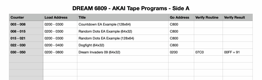
You see, back in 1979, we didn’t have things like an automatic directory of saved programs.
All we had was the Tape deck Counter.
So, we’d normally make a note of the tape counter positions, for each tape we used, to build a hand written record of our saved programs (remember, we didn’t have computers back then!).
As you’ll also note, the new “Dream Invaders09” program, which I’ve also saved, also includes a “Verify Routine”, which we can run to calculate a checksum (in this case stored at memory location $00FF).
This verify routine enables us to verify that the tape load was (likely), successful.
Loading from Tape
Okay, so with the Tape Dump of our first entered program completed, lets test it by turning-off our DREAM re-Creation (loosing the entered program), and turn it back on.
Now if you check the bytes at address 0200 you can see that our program is gone. But hopefully not lost!
So, again, setup the Tape Load start and end locations of 0200 - 0300
So, enter the address 0002 then MEM MOD and then enter 02 00 03 00
Then, rewind the tape to your saved tape counter location.
Press Play on the tape deck, and then press the LOAD function key.
As with Dumping the program, when the Load is completed the DREAM display will update with the LOAD end address 0300
At which point you can stop the tape deck.
And let’s look at the memory at 0200 again.
And, once again, you can see the program in memory.
So, let’s run it again to confirm. So, enter the CHIP-8 address of C800 and press GO
And you’re up and running again.
Now, this time we didn’t change the display mode back to 64×32.
And we also haven’t added the new display mode setting CHIP-8 instruction to the original program.
So what you can now see, is the original program, but running in the top left corner of the higher resolution 128×64 screen.
Modifying our First Program for 128×64
So, now is a good time to show how simple it is to modify the program to now work in the higher resolution 128×64 mode.
So, if we step through the program from 0200 we can first change the random X co-ordinate range from 3F to now be 7F so we are changing from a 64 (0 – 63), X co-ordinate range to a 128 (0 – 127), X co-ordinate range.
Likewise, at 0203 we want to change the random Y co-ordinate range from 1F to 3F
Now we exit MEM MOD mode, by pressing any other Function key, and we can re-run the program with C800 GO
And we now have a High Res 128×64 Random Dot display. Again, please watch the Video (linked above), to see this in action!
We could (of course), choose to now save this version to tape.
But instead, I’m going to enter a new program.
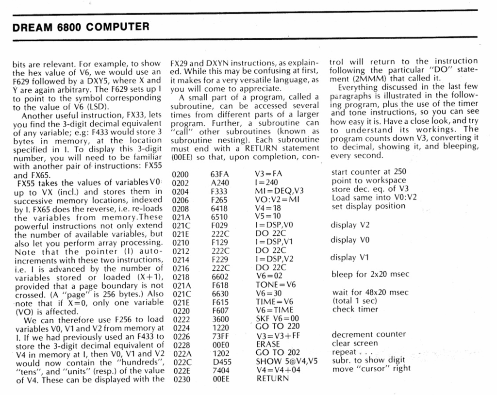
A 2nd CHIP-8 Program Example
So, let’s now load another “Electronics Australia” example CHIP-8 program.
This one creates a count-down timer from 250, and featured in the 4th 1979 article on the DREAM 6800.
Here it is, in the original article.
So let’s key that in, starting from 0200
Now, note that we are currently in Hi-Res mode (after our earlier Reset), and we haven’t added the new display mode change CHIP-8 command.
So, when we run this 64×32 resolution program, we mightn’t get the expected result!
Let’s see. As usual, enter the CHIP-8 address C800 and ten press GO
You should then hear that we have a countdown timer (with a beep every second).
BUT, you’ll note the display is a mess, as demonstrated in the Video (linked above).
On closer inspection of the program we can see that the decimal characters being displayed, are being truncated and overlapped.
That’s because the low resolution font is 3×5 pixels, and our high resolution font is 6×10 pixels.
On reviewing the program listing, we can see it is spacing the characters only 4 pixels apart (at address 022E), and only displaying the first 5 rows of each character (at address 022C). No wonder we have a mess!
Fixing our 2nd Program for 128×64
To fix the unreadable display, we simply need to double the number of rows to display, to 10, and also double the character spacing to 8 pixels.
So, lets do that, by modifying the two mentioned instructions at 022C & 022E These should now be changed to D45A & 7408 respectively.
Now if we run it, we can see our expected 250 and descending count-down.
Finally, to complete the 128×64 adjustment we could also double the co-ordinates of the countdown display position, so the countdown display is more centred, just like the original 64×32 version intended.
To achieve this, simply change the two instructions at 0208 to now be 6430 & 6520
Okay, that should, by now, have given you a good introduction to CHIP-8 programming, and also modifying existing CHIP-8 programs to run with a higher resolution display.
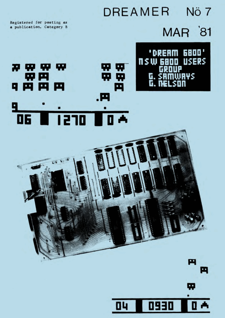
Next, I’ll mention the Dreamer newsletter.
“Dreamer” Newsletter
The “Dreamer” Newsletter was published in 19 issues, between September 1980 and 1982, providing support and publishing plenty of community shared programs for the users of the DREAM 6800.
My first Computer Game
What was of nostalgic interest to me, was that the first Computer Game that I ever wrote, was one I wrote in CHIP-8 for the DREAM 6800.
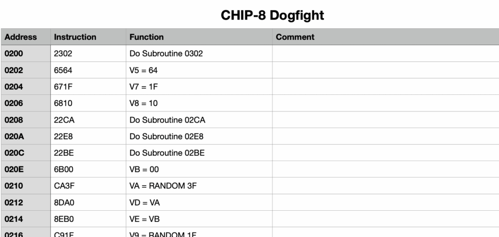
I called it “Dogfight“, and it was eventually published in Dreamer No.17 in January 1982.
Here’s the page from Dreamer, with my Dogfight Program.
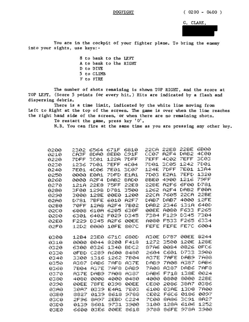
So, I type this all in (just as we did back then), and it’s now saved to my tape.
Interestingly, it didn’t actually work first time.
So, to figure out why, I manually “Disassembled” the program, and that brought to my attention a number of Machine Code subroutine calls.
DREAM 6800 CHIP-8 Machine Code Subroutines
In writing the program, way back around 1980, I had made use of the CHIP-8 ability to call Machine Code subroutines.
As my DREAM 6800 re-Creation has been implemented on the newer, more powerful, 6809 microprocessor, the original machine code instructions were not all compatible.
Firstly, because the 6809 is not fully binary compatible with the 6800. Secondly, the standard CHIPOS Subroutine addresses have changed (as explained earlier).
To explain further, while converting the original CHIPOS code from 6800 to 6809, and also modifying the code for the new hardware implementation, the original “hardwired” CHIPOS subroutine call addresses have (of course) changed.
To ensure that any further changes to the CHIPOS code, does not again change published standard subroutine calling addresses, I took the approach of creating a fixed address Jump Table for all of the published CHIPOS subroutines (as explained earlier).
This will solve the issue going forward.
It’s also worth noting that adding a subroutine jump table wasn’t possible in the original CHIPOS implementation, simply due to the limited space in the original 1K ROM (as also explained earlier).
In addition, the op-codes of some 6809 instructions have changed, from what they were in 6800. In some ways, it’s actually surprising how many op-codes remain unchanged, even though the instruction mnemonics have changed.
e.g. An ‘A’ accumulator immediate load instruction was LDAA #$3C on the 6800, but on the 6809 it is now LDA #$3C
Despite this change in Assembly Code mnemonics, the op-code byte for an immediate data load of Accumulator A, is still $86
This is similar for all of the 8-bit Accumulator instructions. However, the op-codes for loading the X Index register has changed.
e.g. The immediate data load of the 16-bit X index register was $CE on the 6800, but it is changed to $8E on the 6809.
Correcting Machine Code Subroutines for DREAM 6809
As explained, in order to solve the initial failure to run “Dogfight“, it just required me to locate the Machine Code Subroutines, and amend the appropriate bytes for 6809 machine code, instead of the old 6800 machine code.
Here is an example of one of the identified Machine Code Subroutines, and in the right hand column are the byte changes needed to correct the program to run on the 6809.
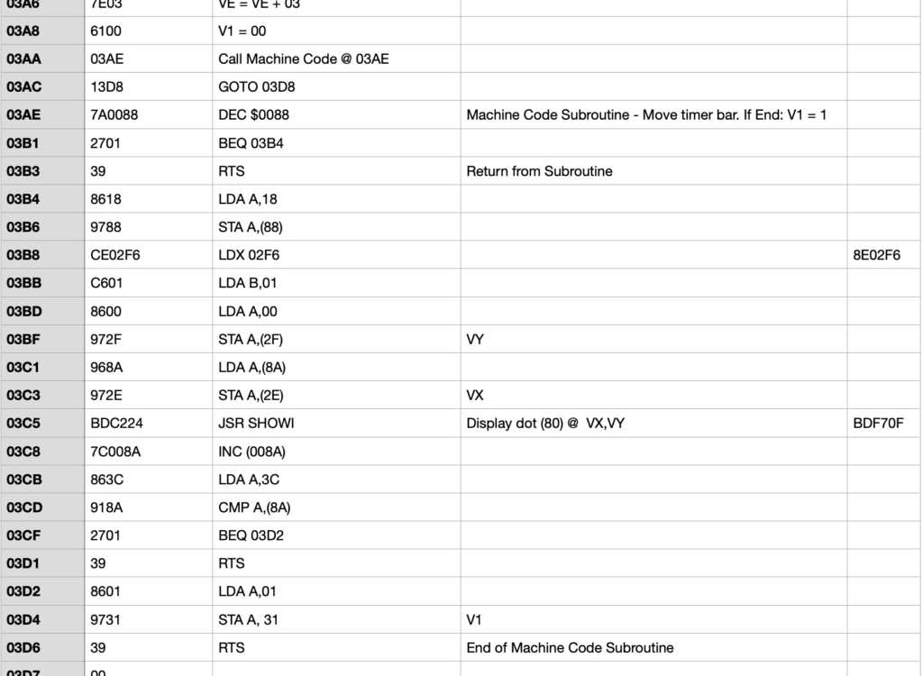
With a total of four Machine Code Subroutines located, and all amended for equivalent 6809 op-codes, my “Dogfight” game was finally up and running!
And, another surge of nostalgia! 🙂
A Bigger Challenge – DREAM Invaders!
Now, let’s take a look at a bigger challenge.
Having first played with and proved that CHIP-8 was functioning (as expected), on my DREAM 6809 (re-)Creation, I decided I’d really love to try converting the original “DREAM Invaders“.
“DREAM Invaders” was a 1.5KB 6800 Machine Code game, written by Michael.J.Bauer in 1980. It even required the original DREAM 6800’s 1KB RAM to first be expanded (e.g. with an Electronics Australia Dec ’80 published 4KB Memory Expansion board project). This was before you even had the memory space required to load “DREAM Invaders”.
So, I dived into making this a bonus extra for my DREAM 6809 (re-)Creation.
Here is the header comments for my DREAM Invaders09 conversion.
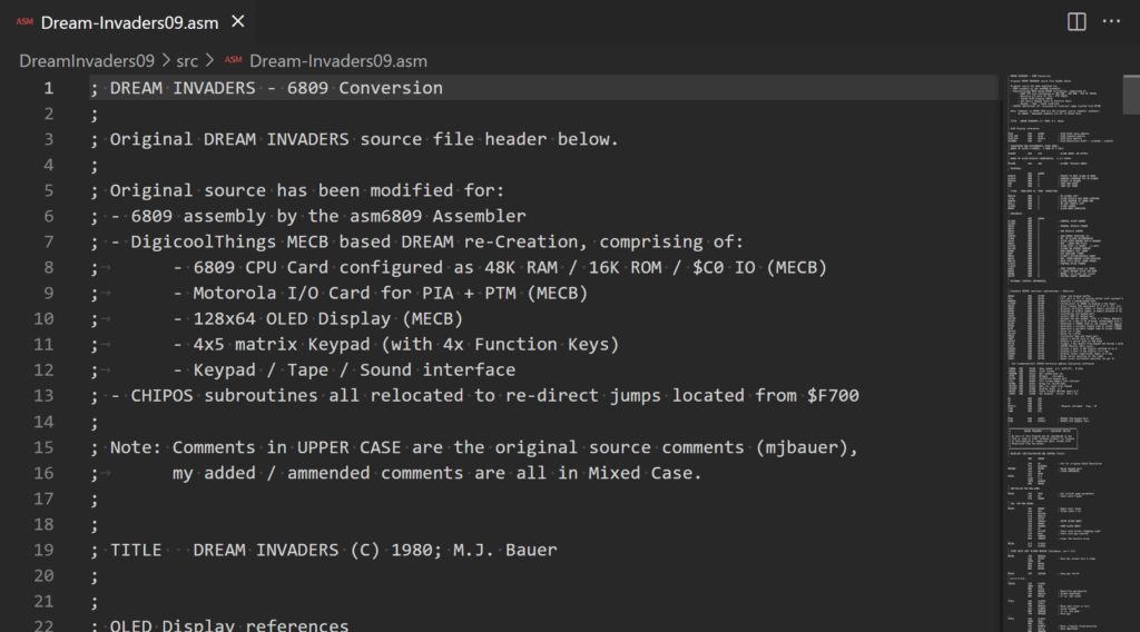
First, I had to locate the original DREAM Invaders 6800 source code, and then convert it to 6809 code which was also compatible with my favorite asm6809 Assembler.
Secondly, I had to work through the code, to change any CHIPOS subroutine call addresses (as outlined earlier), to their new Jump Table addresses.
Finally, I had to identify any other code changes that were required, to support the hardware changes implemented on my DREAM 6809 (re-)Creation.
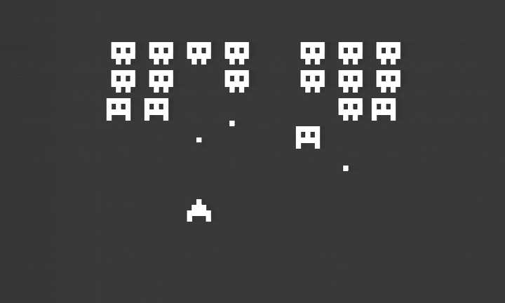
And, success!
I now had “DREAM Invaders09”, running on my re-Creation!
It’s really awesome and nostalgic fun!
Be sure to watch the linked Video (above), if you want to witness the fun!
A future challenge, either for me or for somebody else, is to enhance DREAM Invaders09 to take advantage of the new 128×64 resolution possibilities.
I can just imagine the improvement that higher resolution Aliens would provide!
But for now, I think it’s time to finish off this blog with a game of DREAM Invaders.
Summary
So, if your interested in creating your own early retro experience. Either for re-living your own experience, or, going early retro for the first time, then be sure to check-out the Keypad / Sound / Tape interface on my Tindie Store.
Be sure to also check-out the other components of my DREAM re-Creation.
There are many other CHIP-8 programs to explore, and a lot of fun and also educational programming challenge to be had, from coding your own CHIP-8 creations.
You could even have a go at enhancing the “DREAM Invaders09” code for higher resolution and more features, using the 6809 based DREAM re-Creation’s added processing power.
As usual, you’ll find all the resources, including all source code, on my Github repository for this project. You’ll also find ROM images (for the different MECB 6809 CPU Cards), in their appropriate folders on the MECB Github repository.
And, if you’d like to support me, please do consider looking at the PCB’s and kitsets available from my Tindie store.
Okay, time to play…