
A DREAM 6800 re-Creation, upgraded to a 6809 and higher resolution graphics, but still keeping true to the original 1979 experience of one of the first stand-alone video graphics based microprocessor systems.
Based around a new Keypad Interface + Sound and Tape Interface module, designed for your early retro microprocessor creations.
In Part 1, I cover the design journey, the assembly of my v2.0 finalized PCB design, then testing and aligning the assembled interface. Creating a compact, all-in-one, retro computing I/O module. Finally, fitting the Hex Keypad 4×5 Matrix, and attaching to my MECB Motorola I/O Card’s PIA connector ready to power-up as a DREAM 6800 (6809) re-Creation.
A seperate Part 2 (linked below), covers the CHIP-8 interpreter, CHIPOS operating system, and most importantly, coding on and using the system, accurately recreating the late 70’s experience of using one of the first video graphics based microprocessor systems.
Introduction
It’s been a little while since my last video. But, that’s because I’ve been busy with this project, having amazing fun with developing it, coding for it, and just using it.
I finally feel that all of my hard work is now ready to share. Hopefully, this project will be either of nostalgic interest, or educational interest, to others, who’ll get as much enjoyment as I have.
So, following on from my last couple of videos, where I first introduced my OLED 128×64 Display Card, then, in my last video, I introduced my updated 4×5 Matrix Hexadecimal Keypad.
I’m now, at what probably could be considered, a part 3 of a video series.
I now make use of the two prior projects, for my latest retro system re-Creation.
There was a sneak preview at the end of the OLED Display Card video, where I’d already started to experiment with some existing code.
As you may have guessed, my updated Hexidecimal 4×5 Matrix Keypad project was inspired by my desire to recreate (and re-think), the DREAM 6800.
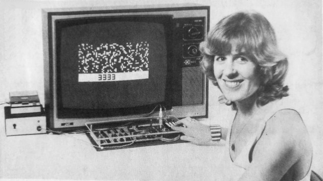
The DREAM 6800 was created by Michael.J.Bauer, and published as a project in the ‘Electronics Australia’ magazine, in 1979.
The DREAM 6800 was my first hands-on microprocessor experience, and it was also one of the first Video Graphics capable microprocessor systems, way back in the late 1970’s.
For the Americans watching this video, the DREAM 6800 was inspired by the RCA COSMAC VIP System.

Both implemented the CHIP-8 higher-level byte language. CHIP-8 was ideal for writing the early chunky video graphics based video games.
One advantage I personally believe the DREAM 6800 had, was that it was based on the Motorola M6800 microprocessor, which was a more traditional 8-bit microprocessor design of the time, as compared to the more unique RCA 1802 that was used by the RCA system.
For this video, I’m actually going to approach things a little differently than my usual video format.
I’ll first go over the design, but then I’ll focus more on the code and the experience of using the finished system, rather than my usual focus on actually building it.
I will, of course, still cover the assembly, but in a quicker format, so that we can move right on to the retro 70’s experience that the system provides.
The re-creation of the DREAM 6800 not only provides a nostalgic experience for those that grew-up during the late 70’s, but it also provides a highly realistic experience for those who just want to experience the early days of microprocessor based computing.
Reaching out to the original DREAM 6800 Designer
In the lead-up to my desire to recreate the DREAM 6800 on an MECB based system, I reached out to the original DREAM 6800 creator, Michael Bauer.
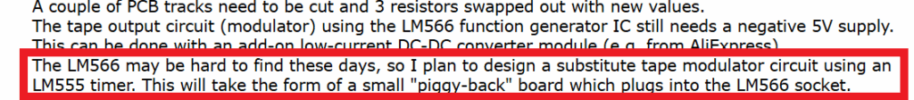
Initially, the contact was primarily to enquire about his website published comment regarding an alternative circuit, to replace the now hard to find NE566 Function Generator (or voltage-controlled oscillator), as used in the original design.
This lead to further email discussions, which also covered some retrospective on early design decisions.
This was very inspirational. One of the first inspirations was Mike’s comment about potentially using a 4×5 matrix keypad to provide an additional row of 4 function keys. This would be instead of the original design’s hardware debounced single function key.
The CHIPOS operating system, which the DREAM 6800 implements, uses the single function key in combination with the 0 – 3 hex keys, to implement 4 different functions. Function 0 through Function 3.
So it did seem a logical enhancement to instead provide 4 dedicated function keys, implemented as an additional row of the scanned keyboard matrix, with software debounce.
Further discussion was had around the original interface circuit design, as several of the IC components, that were used back in 1979, were now very hard (or expensive), to source.
The result was designing a new interface, using only currently available components, and also dropping some of the components that were no longer needed.
It’s fair to say that the new design evolved over time, as design issues were identified and resolved. The result being that my first release is as a version 2.0 schematic and PCB.
For reference, here is Michael’s original schematic for the matrix keypad, tape interface, and the sound interface, for the original DREAM 6800.
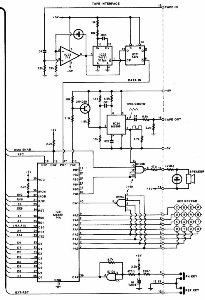
As you can see, it uses the now very hard to find NE566 Function Generator, a 741 dual supply op-amp, as well as a 7440 dual 4-input NAND gate, and a 74121 Monostable Multi-vibrator.
The 74121 is still available, but it’s now relatively expensive.
In addition you can see the choices used for hardware debouncing a standalone single function key.
Note also, that the original circuit used a dual supply of +5V and -5V for the tape interface.
New Circuit Design for Keypad / Sound / Tape Interface
So, here is the V2.0 schematic for my DREAM re-Creation Keypad, Tape, and Sound interface, which I’ve finally arrived at, for the Interface circuitry used for my DREAM 6809 re-Creation.
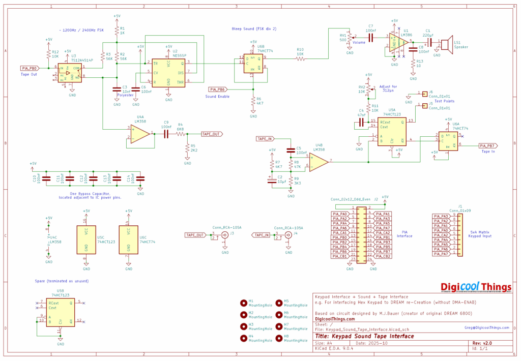
Firstly, I’ve designed this to be driven from the PIA connector on my existing MECB Motorola IO Card, and also to work with my newly added Hexadecimal 4×5 Matrix Keypad.
Secondly, you’ll also notice I’ve included an onboard amplifier and speaker, so it makes for a self-contained board that implements all of the required interface components for a MECB based DREAM re-Creation!
Also, you’ll note it is now powered from a single 5V supply, as we have on our MECB system.
Apart from this you can see that a commonly available NE555 timer, combined with a bilateral switch (both in DIP8 packages), replaces the Frequency Shift Keying function of the original NE566.
In addition I’ve replaced the 74121 with the relatively cheap and commonly available 74HCT123. Also the 7474 has been replaced with a modern matching 74HCT74.
Finally, the original dual supply 741 op-amp, has been replaced with a common LM358 single 5V op-amp. This part of the circuit, is borrowed from Mike’s earlier published single 5V changes to the original design.
Some other changes I’ve made were to utilise the spare 74HCT74 flip-flop for digital control of the sound output. This replaces the prior use of a 7440 NAND gate, and also has the benefit of implementing a divide-by-2 on the resulting sound frequency.
I personally found the Bleeps to be a bit ear piercing, so dividing the default sound frequency (2400Hz) by 2, made for a more pleasant Bleep sound.
New “Keypad / Sound / Tape Interface” PCB Layout
Okay, so let’s move onto the PCB layout.
Here you can see the 3D render of my resulting PCB layout.
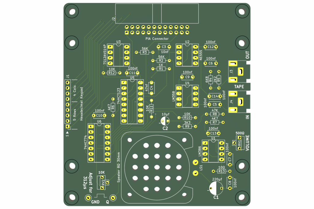
Firstly, note that the PCB is designed to fit underneath the Hexadecimal 4×5 Matrix Keypad, making a nice, tidy & compact interface solution, with all of the circuitry and speaker sound output, all hidden beneath the keypad.
You simply connect the resultant module to the MECB Motorola IO Card’s PIA port, in the same way as my earlier implemented CreatiVision re-Creation’s controller board.
Then you just have the 2 RCA connectors at the side, to connect to a tape deck, for a realistic retro experience, or for connecting to a PC sound interface.
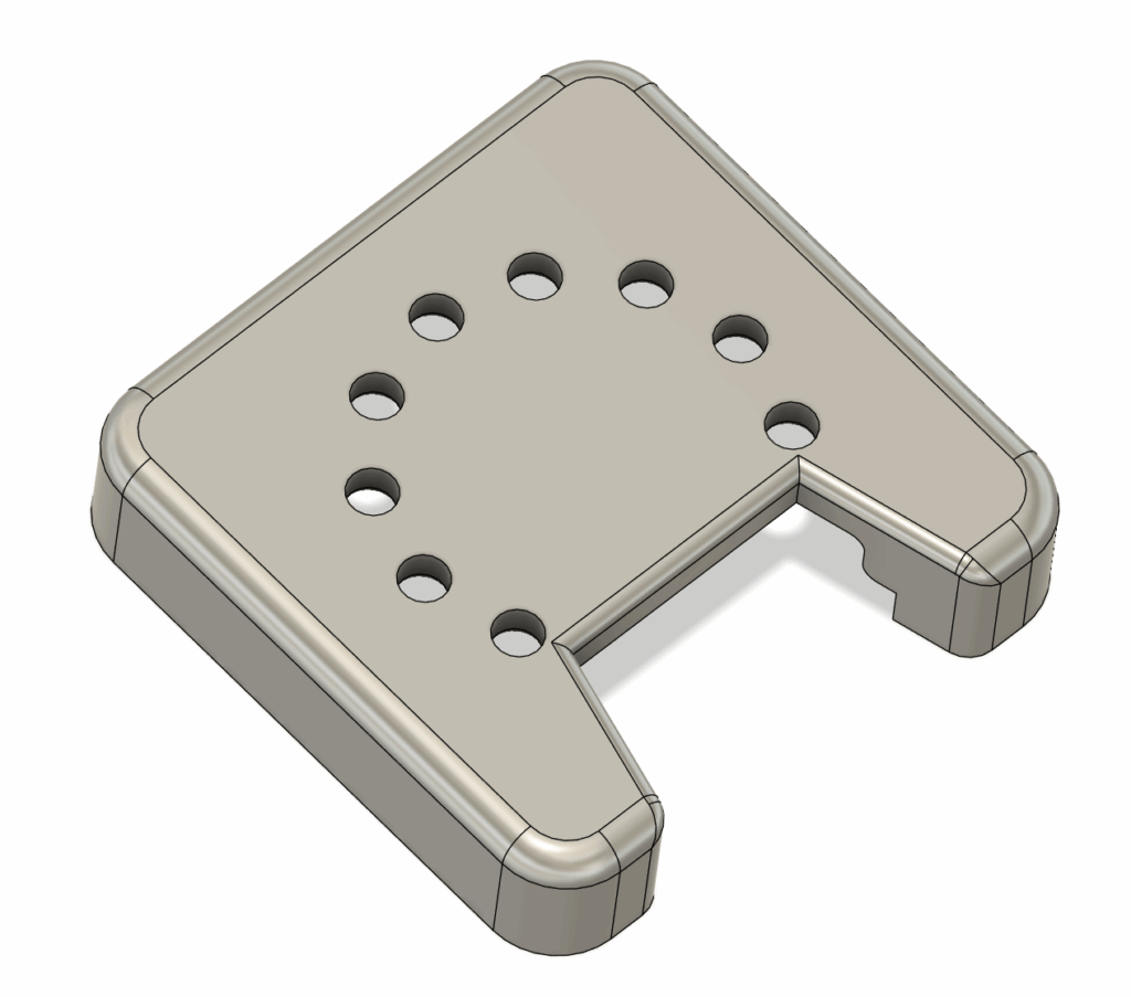
For the speaker mounting, I’ve also created a 3D printed speaker shroud, which nicely holds the speaker to the circuit board.
So, next, lets get one of the new interface cards assembled.
The following optional kitset packs, show all of the components necessary for assembly.
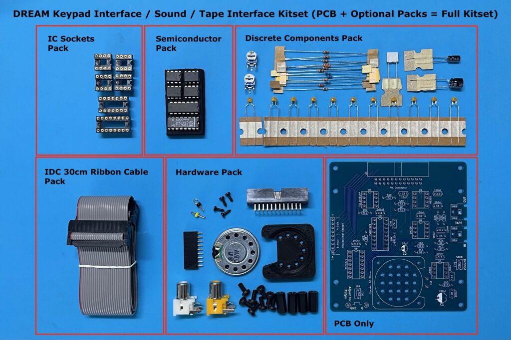
First “Keypad / Sound / Tape Interface” Assembly
In the above linked video I demonstrate the assembly order, that I used for assembling the PCB.
I also note additional details regarding assembly, and then go through testing and adjusting the monostable pulse width.
So, be sure to view the video, if interested in this detail.
I’ll just note a couple of key assembly notes here.
Firstly, note that I have created a couple of PCB edge notches for the RCA sockets. This allows the sockets to nicely clip-in and sit a little lower, ensuring clearance for the KeyPad with it’s supplied 12mm spacers.
Secondly, I attached the speaker connections using a couple of the resistor lead offcuts.
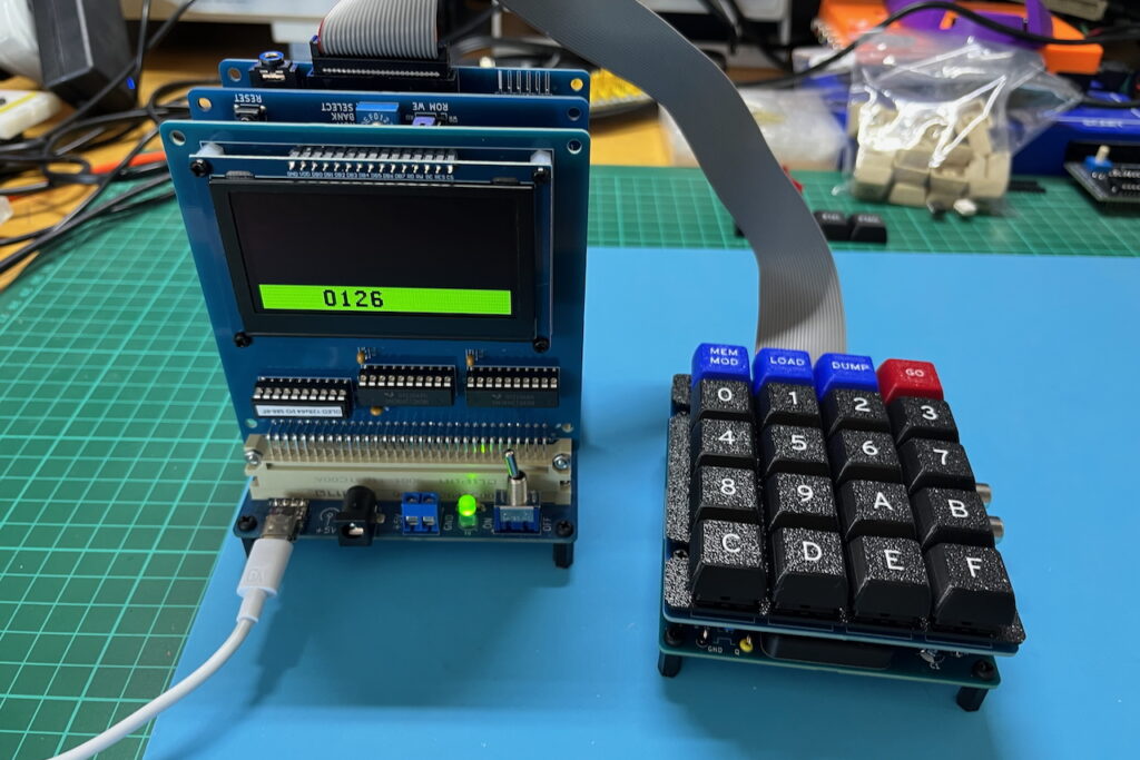
Finally, I fit the Hex Keypad 4×5 Matrix, and attach the completed module to my MECB Motorola I/O Card’s PIA connector, ready to power-up as a DREAM 6800 (6809) re-Creation.
Part 2…
In Part 2, I cover the CHIP-8 interpreter, CHIPOS operating system, and most importantly, coding on and using the system.
My experience with my DREAM 6809 (so far), has been very real nostalgia, as I accurately re-live the original 1979 experience!
Part 2 can be found here: DREAM 6800 (6809) re-Creation – Part 2
As usual, you’ll find all the resources, including all source code, on my Github repository for this project. You’ll also find ROM images (for the different MECB 6809 CPU Cards), in their appropriate folders on the MECB Github repository.
And, if you’d like to support me, please do consider looking at the PCB’s and kitsets available from my Tindie store.
RetroChallenge 2025
I also point you to my RetroChallenge 2025 progress blog. This blog covers my weekly progress on this project, so also gives examples of my adventures, coding for, and using, this awesome retro re-Creation project!
You can find my RetroChallenge 2025 blog here: RetroChallenge 2025/10 (RC2025) – DREAM 6800 (6809) re-Creation