
Ever since creating my existing TMS9918/992x VDP Card, I’ve thought that I’d also like to play with the TMS’s more capable successors, the V9938 and V9958 VDP’s. Also known as the MSX-Video Display Processors.
Join me as I present the Design, then assemble a MSX-Video VDP Display Card, and finally write some 6809 Assembly Code to test out my new V9938 or V9958 VDP RGBS Display Card.
What are the V9938 and V9958 VDP chips?
The original TMS VDP chip was chosen for the MSX standard home computers. The success of the MSX standard drove the evolution of the VDP to it’s much more capable successor, the V9938, which became the display processor of the later MSX2 standard.
One of the great things about these MSX2 VDP chips, is their backward compatibility.
So, you can use a V9938 based display card in place of a TMS display card, running the software that was written for the TMS9918 family.
However, the V9938 also greatly expands on the TMS9918 families capabilities, offering more display modes and twice the resolution.
In addition, the V9938 provides a direct linear RGBS output, meaning that output drivers (like the TMS-RGB module that I used with the TMS9918/992x VDP Card), are no longer required in order to obtain a sharp RGBS output. Furthermore, the colours definitely have more pop, when compared to the earlier TMS family display output.
So, in summary, you can use the V9938 in place of a TMS VDP, and benefit from both better colour and sharp RGBS output, with no need for a TMS-RGB module. In addition, you have more display modes and twice the resolution to play with.
The V9938 was then later further enhanced as the V9958, which added a few more capabilities and featured in MSX2+ computers.
V9938 or V9958 VDP Display Card Design
This VDP Card has all the makings for being my new favourite Video Display Card!
So, it was time to get started!
Here is the schematic for my new VDP display card.
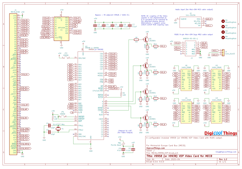
As you can see it contains the usual MECB ATF16V8 PLD chip, for the glue logic.
Then, there is the 64 pin VDP chip itself.
Next, we have four 4464 Dynamic RAM chips, to provide 128KB of VRAM.
Finally, we have the output driver circuitry to deliver the RGBS output, via the same Mini-DIN Sega Mega-Drive2 compatible connector that I used on my earlier TMS VDP card. In addition, I have implemented the same Audio pass-through connection, to allow also delivering the Audio output via the same Mini-DIN cable.
So, a nice clean design, and as mentioned before, no need for a TMS-RGB module (like on the TMS992x VDP Card), in order to obtain a sharp RGBS output.
So, next, here is the 3D render of my newly routed MECB V9938 or V9958 VDP Display Card.
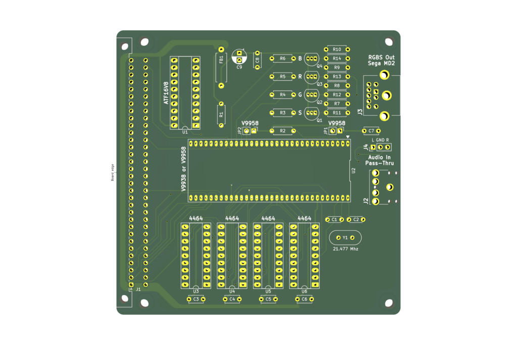
The PCB’s were ordered, and subsequently arrived.
V9938 or V9958 VDP Display Card Assembly
So, on my workbench (below), you can see that I’ve laid-out all of the components packs, except the VDP chip itself, to enable building my V9938 or V9958 VDP Display Card.
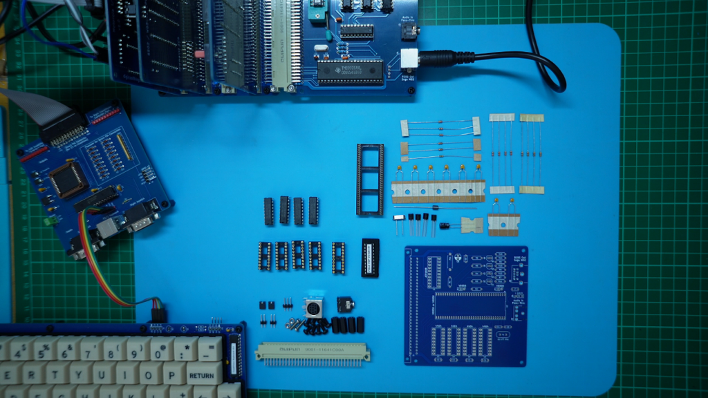
In addition, I need four 4464 64K x 4 Dynamic RAM chips and some IC sockets (as also seen above).
Next, I get one assembled, mounting the components in order of increasing height profile.
Be sure to watch the Video (linked above) for a walk-through of my PCB assembly.
Once, everything was soldered, I inserted the four 4464 Dynamic RAM chips in their IC sockets, which meant all that was left, to complete assembly, was the ATF16V8 PLD and a V9938 or V9958 VDP chip.
Now this is where things got a bit tricky, and significantly delayed my completion of this project.
Obtaining a V9938 or V9958 VDP chip!
The problem was the difficulty obtaining the prized VDP chips!
I actually spent several hundred dollars sourcing V9959 chips, from various suppliers.
They are all pictured on my workbench (below). As indicated, the issue was that they were all wrongly labelled fakes!
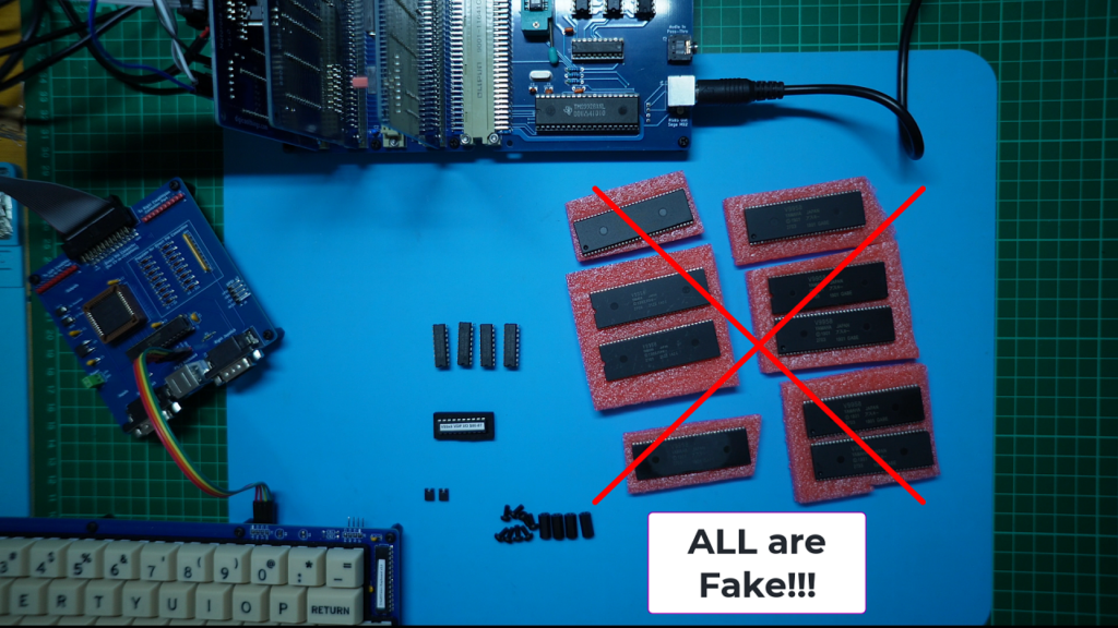
In retrospect, there was a couple of obvious clues that should’ve given them away.
Firstly, the genuine V9959 chips do not have the usual notch in the end, to indicate pin 1.
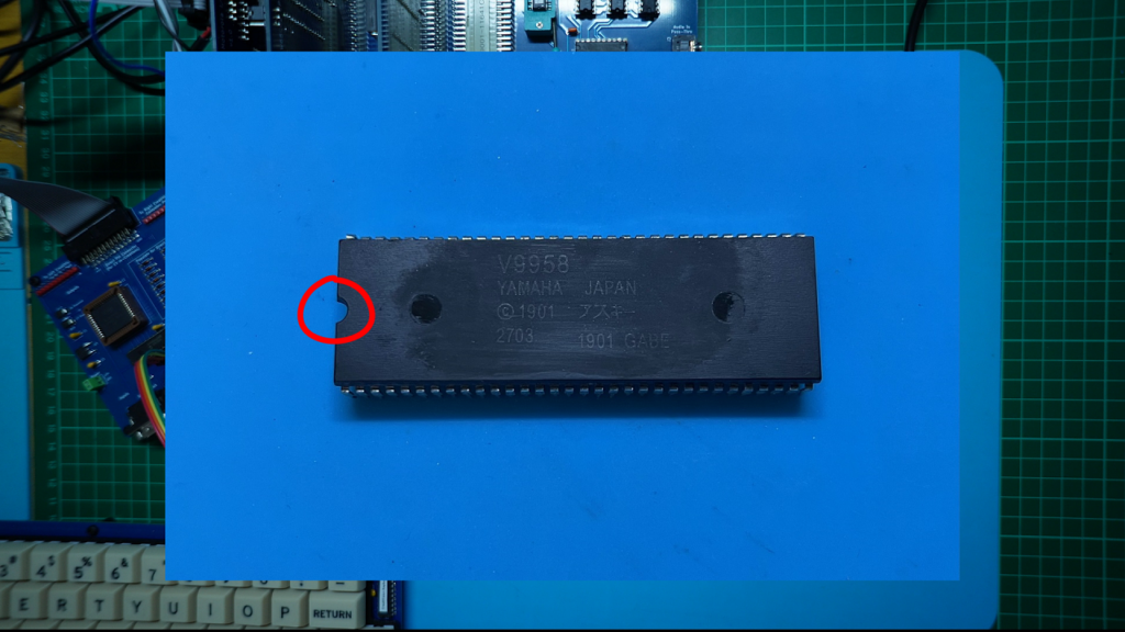
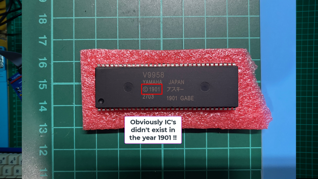
Secondly, the date code of 1901 is a bit questionable, for a chip that was released in 1988.
Unfortunately, I was unsuccessful in trying to get refunds for any of the fake chips I received. Even with these seemingly obvious clues, and my testing of the chips showing no activity, including no clock signal from the pin 8 clock output (which should provide a 3.579MHz CPU clock output), they insisted that I first make a video that proved the chips were not working.
Given the illogical suggestion of making a video to prove that something wasn’t working (as opposed to a video proving something was working), and that I didn’t yet have a working VDP chip to allow showing that my Display Card was actually working, I ran out of time to successfully get my money back.
But, never mind, these costs are one of the frustrations we sometimes go through, in our endeavour to explore retro out of production devices!
So, next, I happened to have a couple of faulty Sony devices, which I’d obtained a few years earlier, knowing that they contained these prized later generation 64 pin VDP chips.
Recovering a “Genuine” V9938 from a failed Sony “My First Computer”
So here is a photo of the inside of my faulty Sony “My First Computer” TV animation computer.
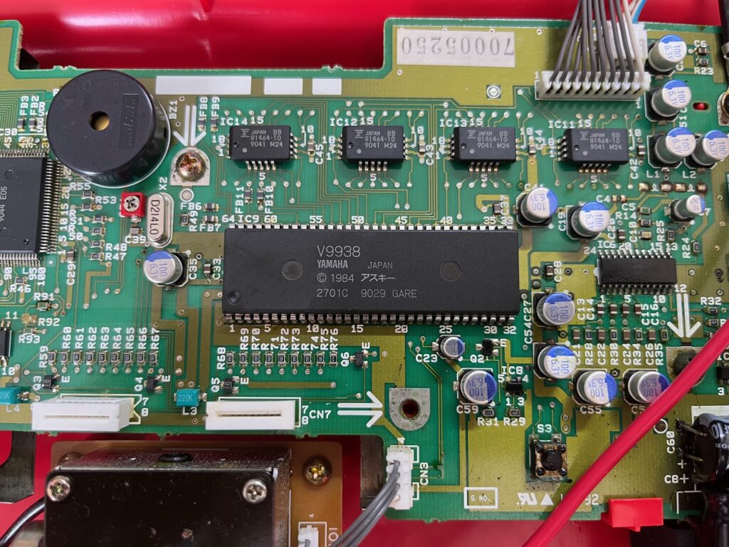
The initial fault in this Sony device was clearly a bunch of leaky electrolytic capacitors, which were also corroding the PCB traces.
I did think about a repair, but at the end of the day it was just the V9938 chip that I wanted to play with, on my MECB platform!
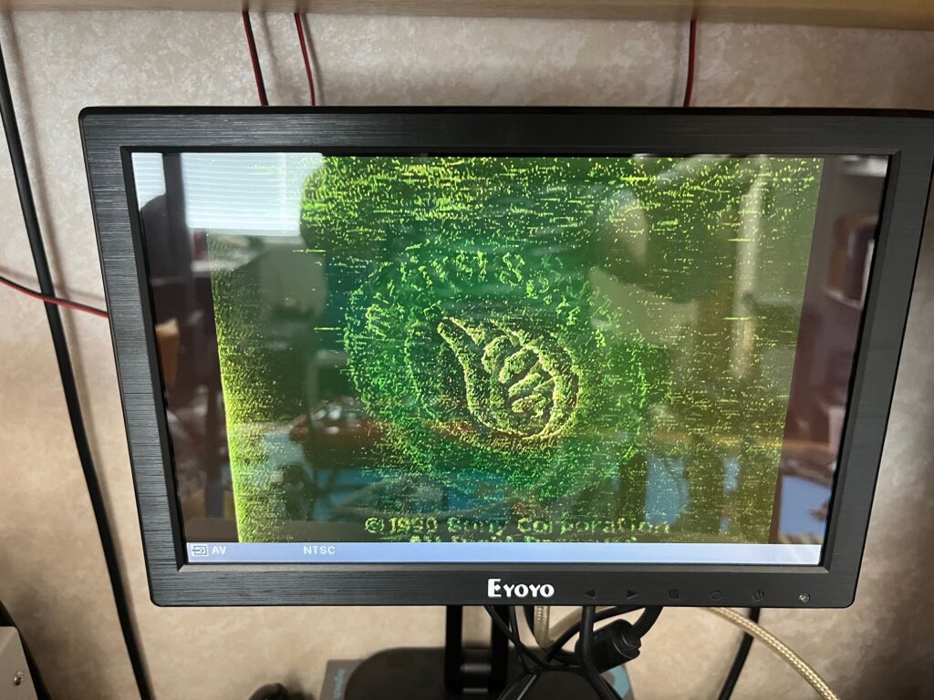
Here is a photo I took of the video output of the Sony computer. Obviously some problems with the video output circuitry, but enough to show me that the VDP chip appeared to still be working!
So, I carefully desoldered the 64 pin IC. I had thought of perhaps installing an IC socket in its place, but unfortunately, getting the chip out successfully involved destroying a few PCB pads and PCB traces.
With my recovered V9938 chip cleaned up, I was at last able to test my new VDP Display Card.
Testing my new V9938 or V9958 VDP Display Card
The first test, was simply to use it directly in-place of my existing TMS9928 VDP Card, with my 6502 CreatiVision re-Creation project!
With the backward compatibility of the V9938, I should be able to simply insert the same glue logic PLD chip, and just swap the Display Card over. All going well, it should just work with the existing CreatiVision TMS VDP targeted software.
So, that’s an easy first test of the new Display Card in operation!
Therefore, I next inserted my recovered V9938 VDP chip into the newly assembled VDP Display Card.
After this, I pulled-out my existing TMS9928 Display Card from my MECB backplane, and swapped the ATF16V8 PLD from it, across to the new Display Card.
Finally, I plugged the new card back into the MECB bacplane.
So, with that new card in-place, I then turned on my 6502 CreatiVision re-Creation.
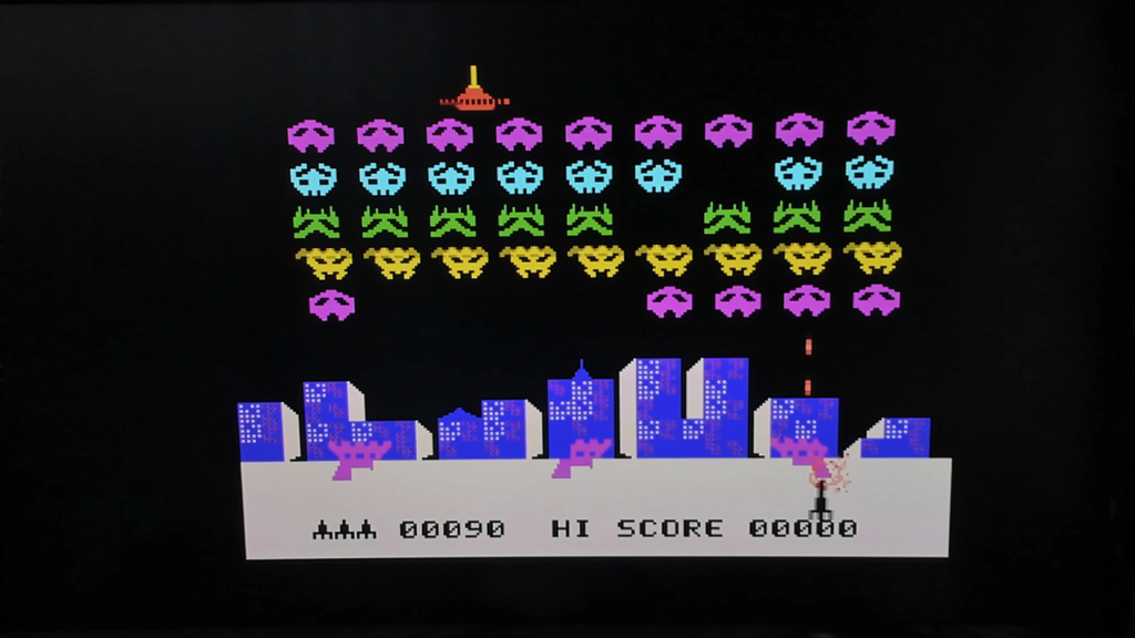
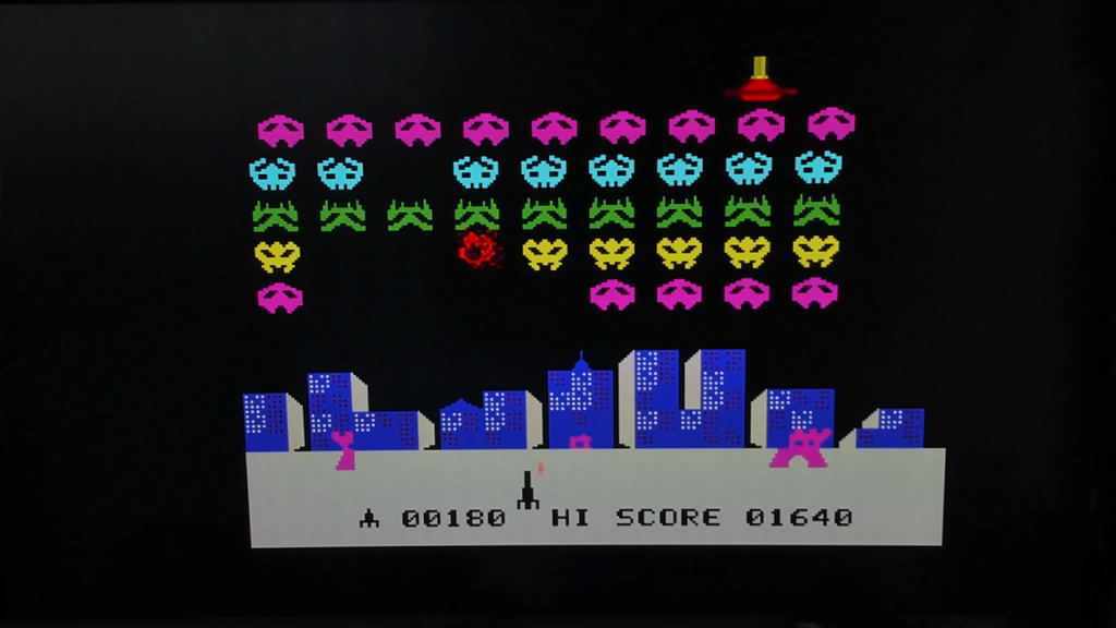
And, I get a nice sharp display of Sonic Invaders, with even more colour pop than the original TMS9928 + TMS-RGB Display card produced.
Below are two screenshots to allow a side-by-side comparison, both captured with my camera set with the same manual settings. In person, the first things that jumped out, were the bolder blues, and also the nice red explosions and red mothership seen on the new V9938 VDP Display Card.
So, with the new Display Card operating as expected in pure backward compatibility mode, the next step was to swap out for my 6809 CPU Card, and write some 6809 code to test at least one of the enhanced modes available with the new V9938 VDP chip.
Writing some 6809 Assembly Code to further test the VDP Card
Next I pulled-out all the MECB Cards from my MECB backplane.
Firstly, I swapped the ATF16V8 PLD on the Motorola I/O Card for it’s regular I/O space $00 - $17 memory map allocation.
Then, I grabbed my 6809 CPU Card, which is currently configured for the $C0 I/O bank allocation.
Lastly, I inserted the I/O space $80 - $87 ATF16V8 PLD into my original TMS9928 Display Card, and inserted that Card into the MECB backplane.
With that done, I was back to a 6809 MECB setup, running the ASSIST09 monitor. Now, I can create a simply “Hello World” test program, that tests the original 40×24 character TEXT mode of the original TMS VDP.
Be sure to watch the Video (linked above), for a walk-through of the 6809 Assembly Code.
With the ASSIST09 monitor fired up, I assembled and transferred the test program, to provide a “Hello World” test in the original TMS Text mode.
This enabled me to first use my original TMS VDP Card, to make sure my code was working properly.
It was working perfectly, so I next substituted the new V9938 populated VDP Card (replacing the existing TMS9928 VDP Card), to check we were still getting a successful “Hello World” display.
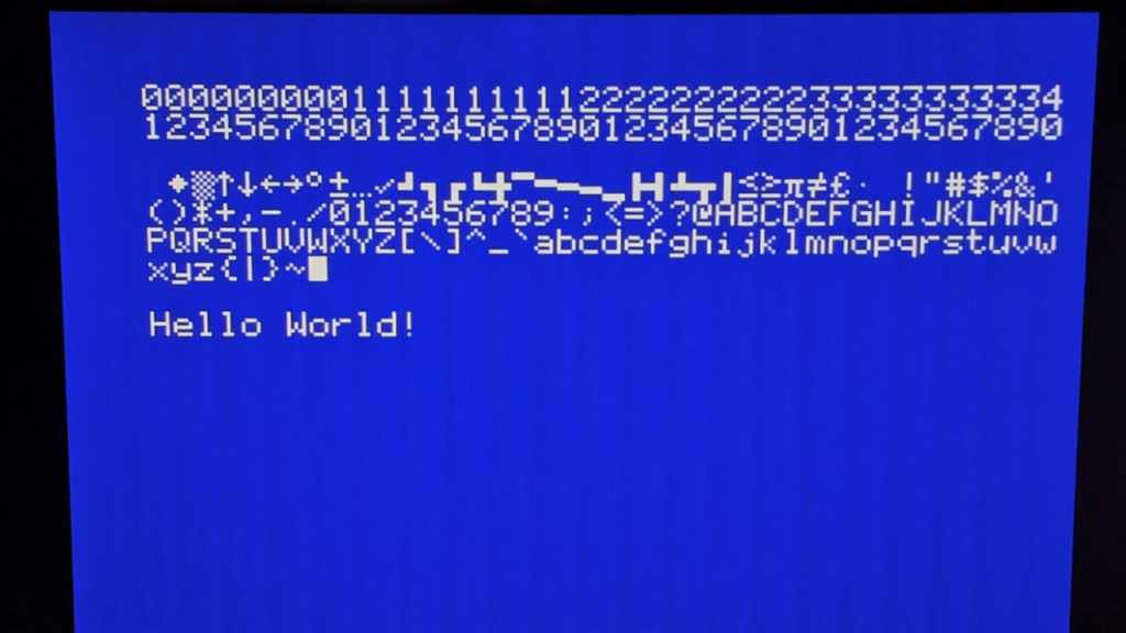
Note, that I also loaded up a 128 character font for the test. Noting that the VDPs are capable of defining 256 characters for its font when in Text mode.
The background and character colour is also selectable. I tried both a normal retro green screen, but I ended up using a white character on a blue background, as I thought this looked really nice, and also captured better with my camera!
So, here’s the “Hello World” 40 column test, running on the new V9938 VDP Display Card.
Now, one of the new modes supported by the double resolution capabilities of the V9938, is the TEXT 2 mode, which now provides a full 80 x 24 character display mode, and also supports blinking characters, in different colours.
So, I modified the “Hello World” test program for testing this new TEXT 2 mode. This version of the code will only work on the new V9939 VDP Card!
Again, be sure to watch the Video (linked above), for a walk-through of the code changes!
The V9938 now provides 45 command registers, as compared to the TMS, which only had 8 command registers. Although not necessary for TEXT 2 mode, I now initialise 23 of the 45 command registers for this test, including setting the required mode bits for the new 80 column TEXT 2 mode.
So, with that code successfully assembled and transferred across to the CPU card, here’s what it looks like.
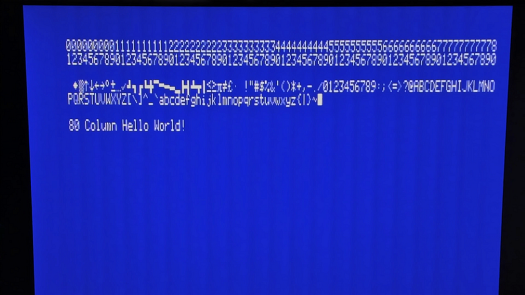
Nice, we now have 80 column text capability!
So, with this test completed, I’m now happy to call my new V9938 or V9958 VDP Card a success, and definitely my new favourite VDP Card to play with!
Sharing the Source Code and V9938 / V9958 VDP Resources
I’ve put the 6809 Assembly Source Code for these two new tests on the DigicoolThings MECB github repository (as normal), along with the PLD source and compiled .jed files, for easy programming with your ATF16V8 compatible EPROM programmer (like my TL866 family USB programmer).
I’ve also uploaded to the MECB github repository, the V9938 and V9958 MSX-Video Technical Data Books.
Tested and Verified as Genuine V9938 and V9958 VDP chips
Now, the really good news. After trying a few suppliers for genuine original V9938 and V9958 chips, I now have a trusted source.
Below, you can see my current stock of MSX-Video VDP chips, all tested 100% working. Aside from my self-recovered original V9938 chips, the rest were all new and original chips. I even had to bend the legs slightly to get them into the Card’s IC socket for testing. So, I’m pretty convinced that the V9938 chips are New Old Stock.
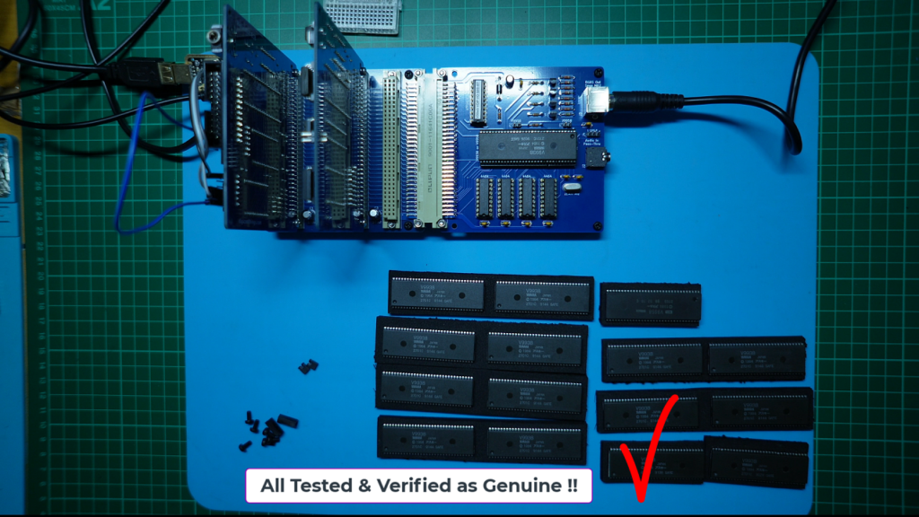
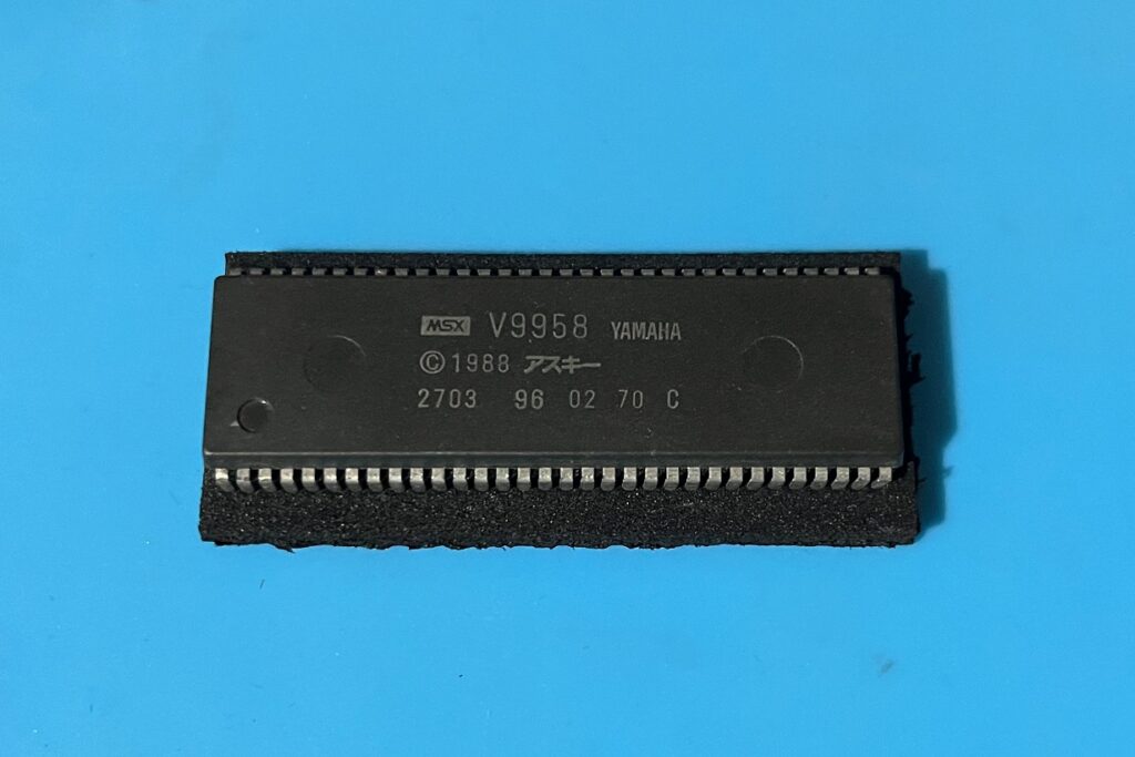
I also have one verified, and more expensive to obtain, V9958 chip. Which also enabled me to verify the new VDP Display Card with its two jumpers in place for V9958 support. All worked as expected.
However, at this stage the V9938 is cheaper, and has plenty more modes than the old TMS family VDP chips to experiment with!
So, I’ve decided that, to support other enthusiasts who are also interested in playing with this awesome VDP chip, I’d add an optional pack to my Tindie Store, for these pre-tested verified as operational V9938 and V9958 VDP chips.
I don’t suspect that I’ll ever recover the money that I’ve lost, with all the fake chips that I bought, but, if you are keen to try my new MECB V9938 or V9958 VDP Display Card, then you can support me by also buying a pre-tested and verified VDP chip from my Tindie Store.
Time to Experiment with more new VDP modes!
So, that’s all for the introduction of my awesome new MSX-Video VDP Display Card, which gives a lot more to experiment with.
Have fun!