
If you are at all interested in PS/2 keyboard interfacing, then this post / video should be of interest to you!
My CreatiVision Mechanical Keyboard was originally intended just for using with my CreatiVision Controller, which only requires one-way PS/2 communication.
But, to allow the PS/2 Keyboard to also be used as a general PS/2 Keyboard, full bidirectional PS/2 protocol communication is required!
So, as I’ve mentioned, this is a follow-up to my CreatiVision Keyboard project, which I completed in late 2024.
This Mechanical Keyboard was the final component of my MECB based CreatiVision re-Creation project.
A member of the DigicoolThings Forum (David), recently asked about the general PS/2 compatibility of the keyboard.
As it turns out, I hadn’t even considered using the keyboard with other PS/2 hosts, as I had designed it just as a CreatiVision specific add-on for my CreatiVision Controller.
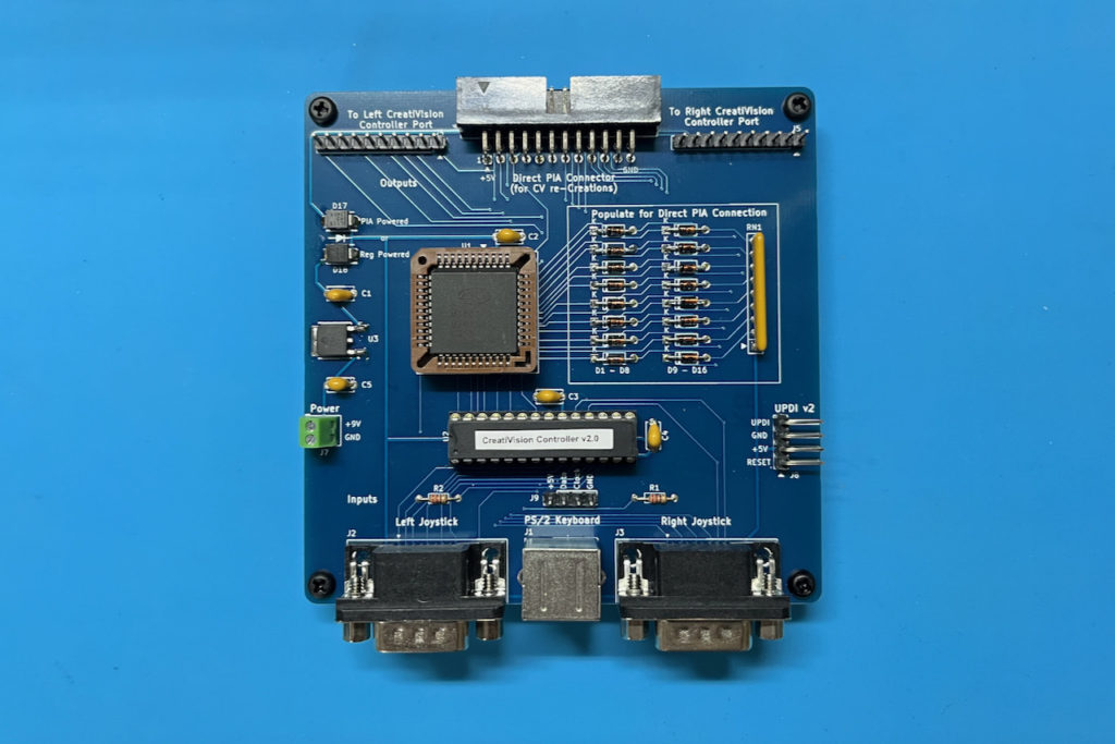
I hadn’t even attached a standard PS/2 mini-DIN cable to the keyboard yet. Instead, I’d always just used it by jumpering across to my CreatiVision Controller card’s PS/2 header, as I’d shown in the Keyboard project video.
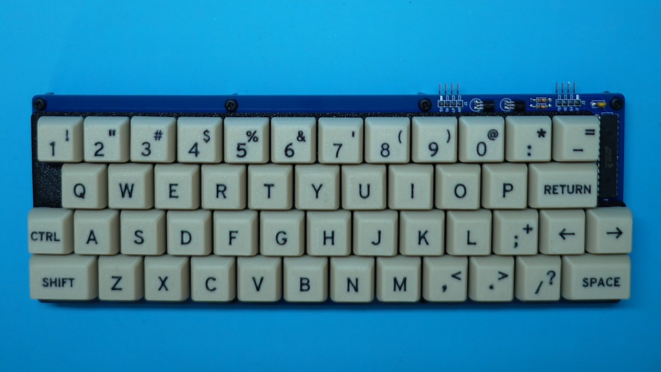
But David’s question got me thinking. Specifically that, this 48-key Mechanical Keyboard could also be quite useful as a compact PS/2 Keyboard, for wider use.
Of course, the custom keycaps that I’ve created are specific to the CreatiVision, so some of the shifted characters differ from that of a regular PC keyboard.
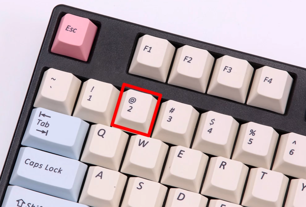
For example, the shifted ‘2’ key is a double-quote (“) on the Creativision keyboard, but on a PC keyboard the same shifted ‘2’ key is a Commercial At symbol (@), as shown below.
However, this wouldn’t stop someone from using this compact 48-key Mechanical Keyboard! Either, used with a PS/2 keyboard interface on other custom retro computers, or, used for a retro PS/2 input PC you could certainly swap-out for a standard set of keycaps.
Swapping out keykaps is of course an option, as I designed the keyboard with standard MX key switches, and with standard key spacing.
So, the current issue with wider PS/2 compatibility, is that I had designed the keyboard with only a unidirectional PS/2 bus interface.
This was for simply sending the standard PS/2 key scan codes, which is all that the CreatiVision Controller requires.
The problem with using the v1 Keyboard with other PS/2 hosts, is that (often), full bidirectional communication is required.
A PC PS/2 host, for example, might send a reset command to the keyboard and await an acknowledgement, before accepting any key scan codes.
To resolve this, I dived into researching a version 2 upgrade of the original CreatiVision Keyboard project, with the goal of fully implementing the bidirectional interface standard for the PS/2 keyboard.
This has been a fun journey! (Thank you David). 🙂
First, I had to (once again), research the PS/2 standard, to refresh my memory.
Then, I had to find some other PS/2 Hosts for testing with.
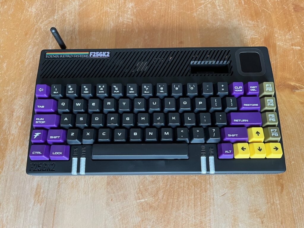
First, I started off with my modern Foenix F256K2 retro computer. Which, despite having its own MX keyboard built-in, also has a PS/2 keyboard interface. So this appeared perfect for starting my version 2 upgrade testing.
So this is my F256K2 looks like:
Interestingly, the F256K2 did respond to my original v1 Keyboard key presses, but it was displaying inconsistent character errors and occasionally got stuck in repeat mode (until another key was pressed).
So, I then hooked up my scope to see exactly what was going on.
It was good to finally see some Host to Keyboard communication, captured after a reset, which of course currently goes unanswered from the v1 CreatiVision Keyboard.
What I did next was to connect my generic PS/2 keyboard to the Foenix. This was the same keyboard that I’d previously used with my CreatiVision Controller Card (before eventually making my Mechanical CreatiVision Keyboard).
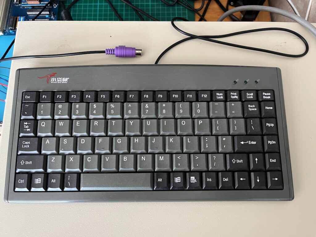
I was then able to see how the generic PS/2 keyboard responded, following computer reset. Also, how it’s key press scan code transmission compared to the version 1 CreatiVision Keyboard.
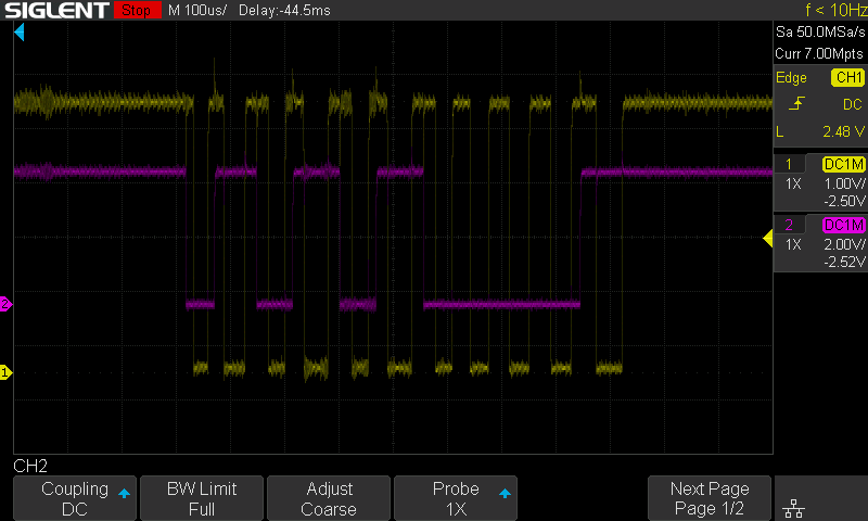
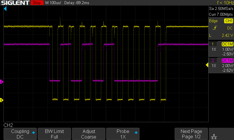
What was interesting, was that the key scan code transmission from the keyboard to the Foenix, looked virtually identical to the CreatiVision keyboard.
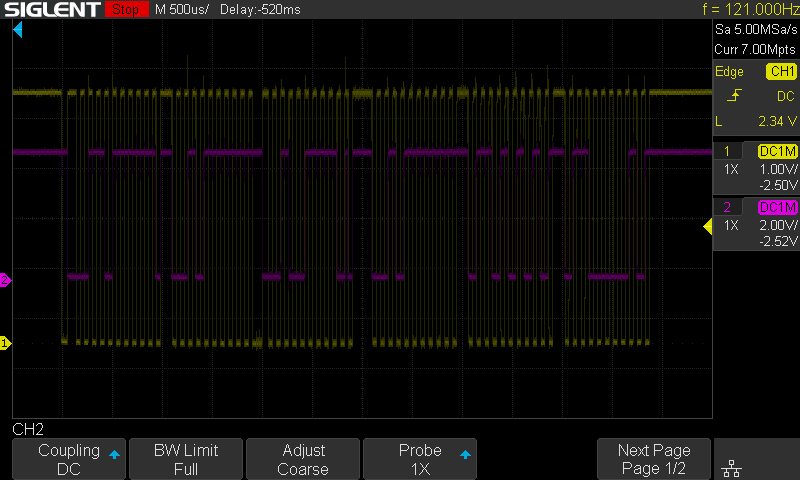
As you can see from my oscilloscope captures of hitting the ‘Q’ key, essentially an identical transmission from both keyboards!
NOTE: In the below scope captures the yellow trace is the PS/2 Clock, and the purple trace is the PS/2 Data. The Data trace is adjusted to half amplitude (2V/div instead of 1V/div), and also vertivally centered, for ease of viewing level / edge timing between the two signals.
Despite the apparent clean and tidy, virtually identical transmission, I was still getting random character errors and repeating keys registering when using the CreatiVision Keyboard with my retro PS/2 input computer.
So, this lead me back to the electrical interface.
For comparing the different devices, I then wired up this interface jig (as seen below), using a small breadboard and helped with a terminal block, so that I could get easy access for measuring and monitoring the different devices.
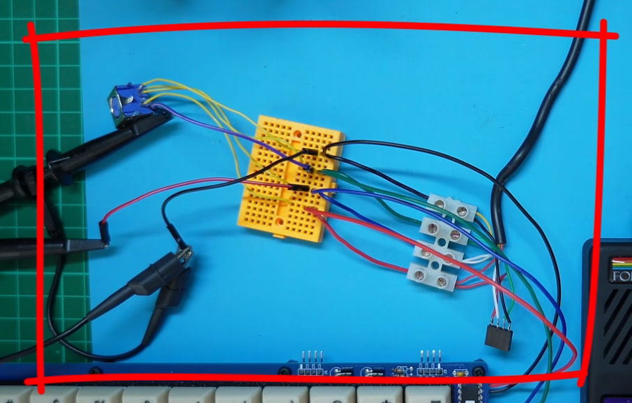
By just measuring the unpowered interface’s apparent pull-up resistance, from the PS/2’s Clock / Data lines to the 5V line, I was seeing:
- 1.2M pull-ups on the generic Keyboard (most likely no pull-ups!)
- 4.7K pull-ups on the Foenix Computer (Host)
- 10K pull-ups on my existing v1 CreatiVision Keyboard (external resistors R1 & R2)
Also, as the Foenix computer is a modern FPGA based retro computer, it would also have the added complication of 5v to 3.3v level translation.
After some more research of the PS/2 protocol and interface standards, I arrived at the same conclusion that I had before. Which is that, 10K is the generally recommended pull-up value. But clearly, this isn’t standard for all devices.
So, at this stage, I decided to park the Foenix’s inconsistent character responses to my key scan code transmission. So that I could first focus on implementing full bidirectional communication protocol.
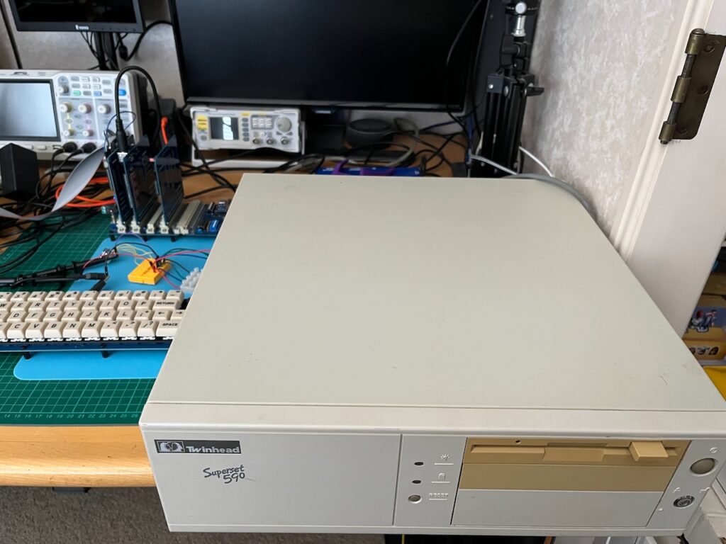
I also dug-out an old 386 PC that I had in storage, with its original PS/2 keyboard interface.
It was a Twinhead Superset 590. A very nice PC in its time, from around the late 1980’s.
This is perhaps a much better Host to use for my initial testing, as it indeed represents an original PS/2 Host implementation.
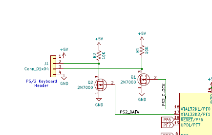
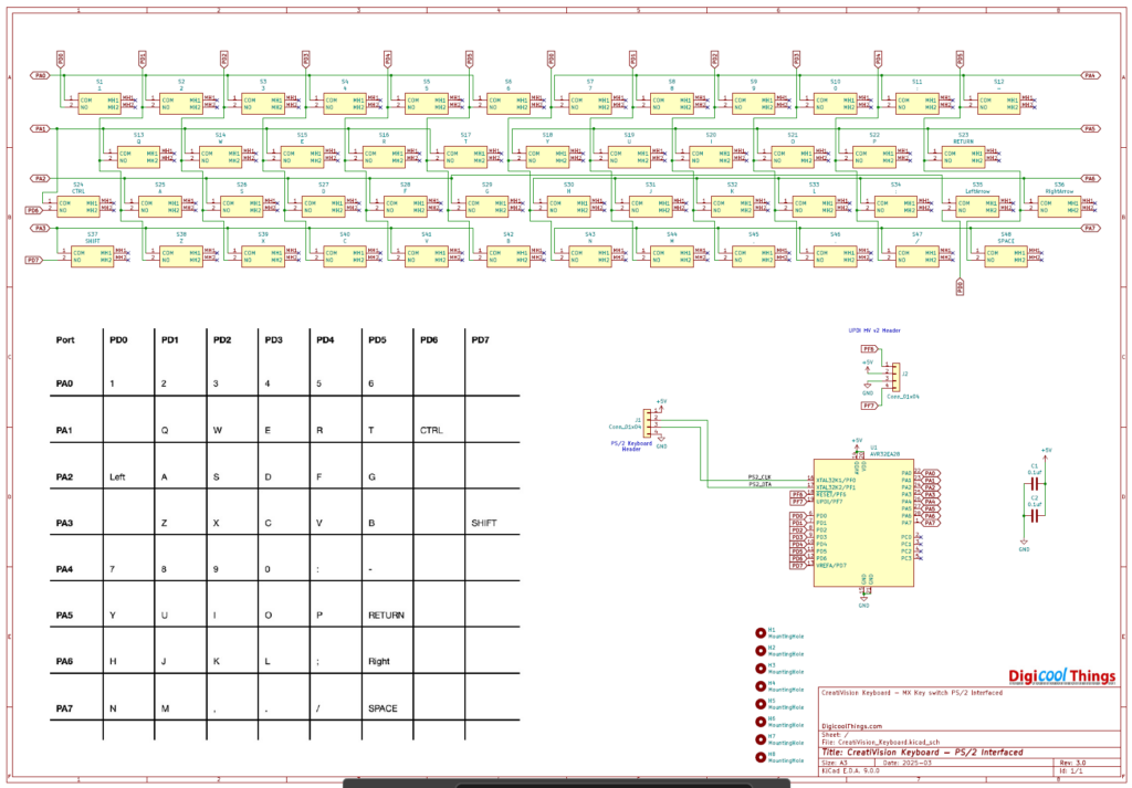
To explore bidirectional communication, I soldered a couple of links to my CreatiVision Keyboard, to connect the currently unused Port C0 and C1 pins directly to the PS/2 bus Clock and Data lines (as shown in the updated schematic below).
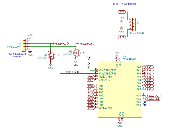
With these Port C pins programmed as inputs, I was then able to directly sense the PS/2 bus signal state.
And, with a some re-coding of my original unidirectional firmware, I was able to now both receive and transmit, following the full bidirectional PS/2 protocol.
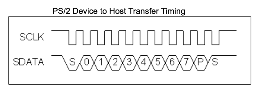
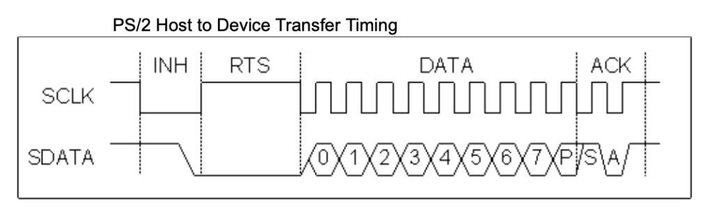
Below is a good representation of the PS/2 signal protocol. Note that the clock is always generated by the Device (e.g. Keyboard), but the Host (e.g. Computer), is fundamentally in control, as it can pull the clock line low, at any time, to inhibit communications.
The Host also pulls the data line low to indicate a request to send to the device.
The Host receives data from the Device after the falling edge of the clock, essentially sampling the data when the clock is low. Whereas, the Device receives data from the Host after the rising edge of the clock, essentially sampling the data when the clock is high.
Testing confirmed a nice healthy exchange of commands and data between the Superset 590 computer, and my new v2 CreatiVision Keyboard firmware code.
Specifically, following reset, I was seeing on my scope, the following handshake:
- From Host –
Reset (0xFF) - From Device –
Acknowledge (0xFA) - From Device –
Self-Test Success (0xAA)
A pause of approximately 5300ms then happens, during the system’s “boot-up” delay.
- From Host –
Read ID (0xF2) - From Device –
Acknowledge (0xFA) - From Device –
Keyboard ID 1st byte (0xAB) - From Device –
Keyboard ID 2nd byte (0x83) - From Host –
Set LEDs (0xED) - From Device –
Acknowledge (0xFA) - From Host –
(0x02)–Num Lock On - From Device –
Acknowledge (0xFA)
All looking really good!
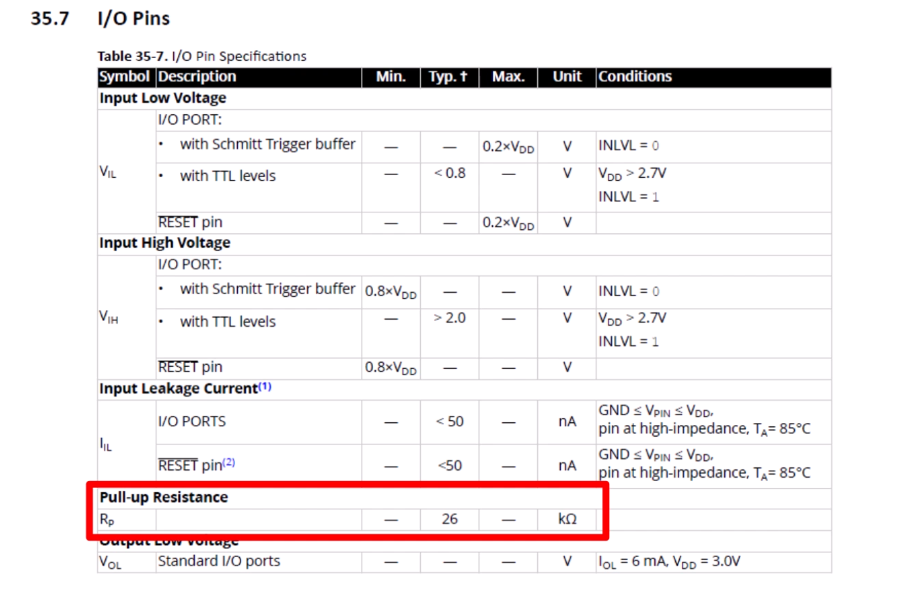
The next thing that I did was take the existing external 10K pull-up resistors out of the circuit, and I instead enabled the internal AVR input port pull-ups.
The internal AVR pull-ups are about 26K, which is a slightly weaker pull-up, than my 10K external resistors, but given that I’d previously measured perhaps no pull-ups were present in the generic PS/2 keyboard, I figured this would be fine.
With this all tested, and the new v2 firmware all well documented and working, I then started updating the schematic and PCB for v2.0.
This involved removing the external pull-up resistors R1 and R2, and routing the Port C0 and C1 pins to the PS/2 connector.
All was completed, and it was time for me to “sleep on” the design changes. Something I’ve learned to always do before ordering a new PCB.
Without a doubt, I always wake up the next morning with a clear picture of further changes, or “tweaks”, I want to make.
This time was no different. I woke up the next morning with a clear view of also removing the external MOSFET open-drain drivers, and instead using the AVR’s port control to simulate an open-collector interface.
This is achieved by using two states of a GPIO pin. Firstly, being programmed as an output pin driving Low, and secondly, with the pin programmed as an input with a pull-up, for the default idle High state.
With this approach, I no longer needed the port C connections, or the 2x 2N7000 MOSFET’s, making a nice and tidy simplification of the design.
Before making this change though, I performed another test with my revised v2.0 firmware code Keyboard, connected to the Foenix Computer.
Now, although I was seeing a good power-up handshake after reset, and nicely formed key scan-code transmission from the CreatiVision Keyboard to the Foenix computer, I was (unfortunately), still getting inconsistent character responses to my key scan code transmission.
This was most frustrating, and lead me to believe this was most likely something to do with the modern 3.3V FPGA based interface, presumably used in the Foenix design, that was causing unreliable Feonix registering of the low level transmission?
So, with that unresolved question mark, I then went ahead with the removal of the MOSFET’s, external resistors, and Port C jumper leads, and just wired the existing Port F0 and F1 pins directly to the PS/2 bus.
I then made the changes to my AVR code to support the new simulated open-collector interface approach.
Since I already created a v2.0 keyboard PCB design and otherwise tested successful v2 code, I decided to progress this new approach to v3.
With this version 3 software re-work completed, it was time for another test.
This time I was pleasantly surprised that my Foenix computer was now working 100% reliably with the new v3 CreatiVision Keyboard interface modifications and supporting v3.0 code.
Yay!
I can only put the earlier issues down to something about the Foenix PS/2 interface design not liking a traditional 2N7000 MOSFET driven open-drain interface?
Curiosity about this nearly got the better of me, but then I realised that it simply wasn’t important. The new approach now worked 100% reliably! That is all that really mattered at this point.
The final test, was for me to reconnect my old Superset 590 386 PC to my new v3 Keyboard, and see how it performed.
Again, a 100% reliable initialisation command handshake, and 100% reliable key scan code communication.
So, the v3.0 firmware update is all done!
Lastly, I updated the schematic for v3.0 and re-routed the PCB for the new v3.0 iteration. Now removing both the MOSFETs, as well as the previous Port C0 and C1 pin routing. The resistors I’d already remove for v2.0.
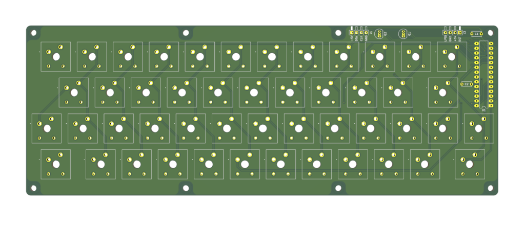
And here is the final v3.0 PCB 3D render.
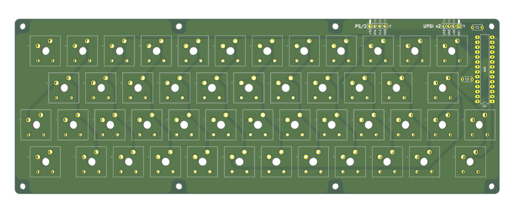
I also took the opportunity to re-align the connectors, which also allowed enough room for PS/2 and UPDI connector silkscreen labels on the top side of the PCB.
So, I now have a successful full bidirectional generic PS/2 keyboard capability upgrade.
Of course, I did also confirm the Keyboard still works with the CreatiVision Controller (as it was originally designed for).
To share the results of this successful v3.0 keyboard update, it’s probably easiest to just show the scope captures of the start-up command handshakes.
I earlier described the Superset 590 boot-up command handshake.
Interestingly, the Foenix F256K2 is a little different. It doesn’t set the keyboard LEDs (like the Superset 590 PC does), but it does add a Set Default Parameters command, and finishes by sending the Enable Keyboard Scanning command.
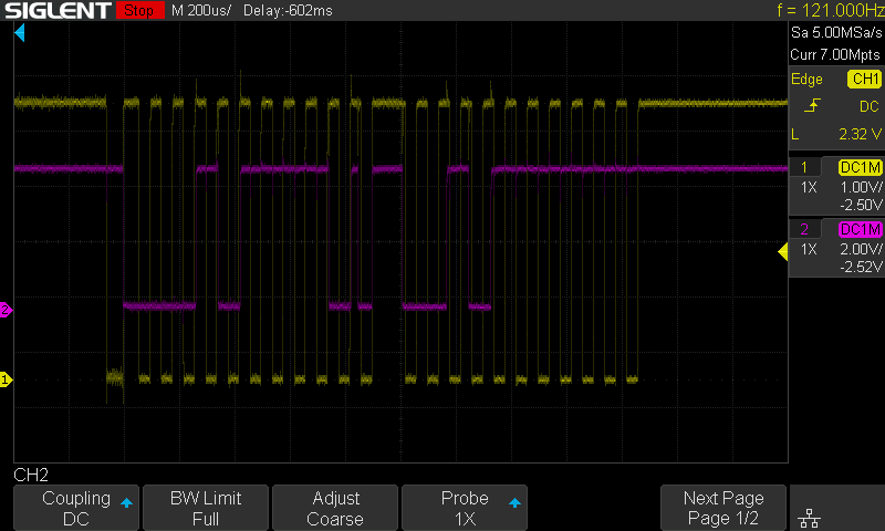
Below is a helicopter view of the three command packet exchanges that happen following the Foenix reset.
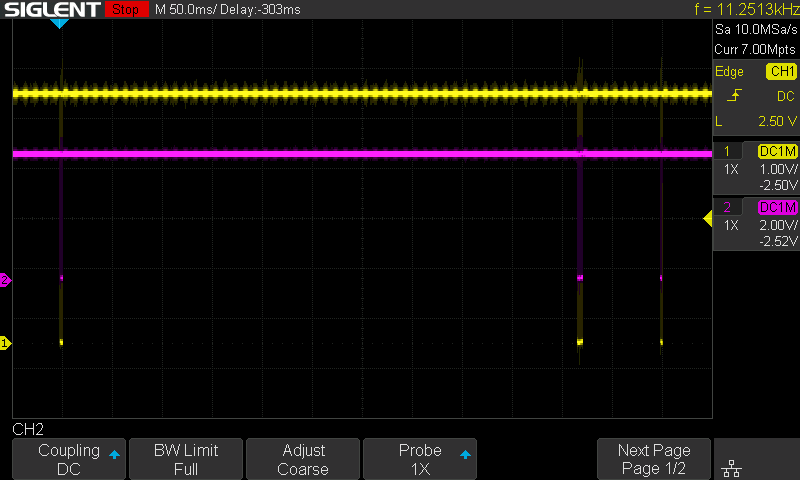
Looking at the first packet (below), you see these 3 bytes exchanged:
- From Host –
Reset (0xFF) - From Device –
Acknowledge (0xFA) - From Device –
Self-Test Success (0xAA)
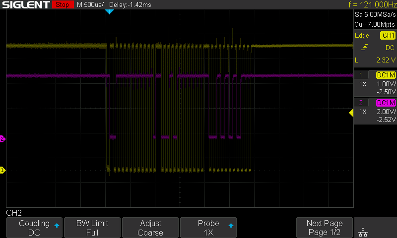
Then for the second packet (below), you see 6 bytes exchanged:
- From Host –
Set Default Parameters (0xF6) - From Device –
Acknowledge (0xFA) - From Host –
Read ID (0xF2) - From Device –
Acknowledge (0xFA) - From Device –
Keyboard ID 1st byte (0xAB) - From Device –
Keyboard ID 2nd byte (0x83)
Then, for the 3rd and final packet (below), you see 2 bytes exchanged:
- From Host –
Enable Scanning (0xF4) - From Device –
Acknowledge (0xFA)
From then on, we just see the appropriate keyboard scan codes being transmitted from the Device (Keyboard), as each key is pressed and released.
Nice!
I’ve now updated the Tindie Store for the new v3 PS/2 Mechanical Keyboard, for anyone interested in a CreatiVision Keyboard, and/or a compact 48-key PS/2 Mechanical Keyboard.
So, to finish-up, I’ll now just cover what will be required by an existing owner of the previous v1 Keyboard, if they want to update to a full bidirectional PS/2 Keyboard solution.
Fortunately, updating your existing Keyboard PCB is relatively easy. But, you will also need a UPDI programmer, to enable programming the new v3 firmware code into the onboard AVR microcontroller.
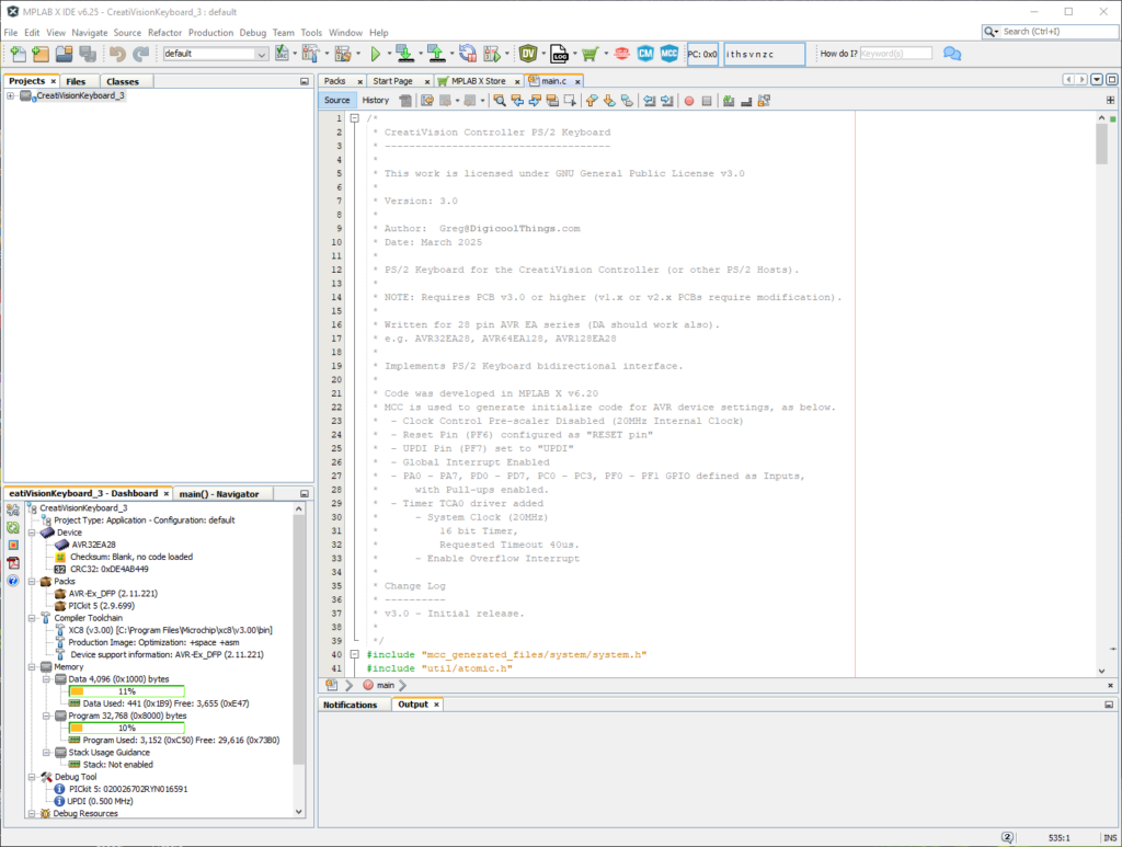
For this I do highly recommend the Microchip PICkit5 programmer. It “just works” flawlessly with the MPLAB X IDE, and it is certainly a lot cheaper than the previous PICkit4.

I’ve had varying success with 3rd party AVR programmers. In fact, if I’d just bought the PICkit5 first, I would have saved a bit of wasted money.
But, if you have success with a cheap 3rd party alternative programmer, please share via the Forum. Others will probably be interested.
Once you are able to successfully program the AVR, then the modifications to the v1.x PCB, to bring it up to v3, are simple.
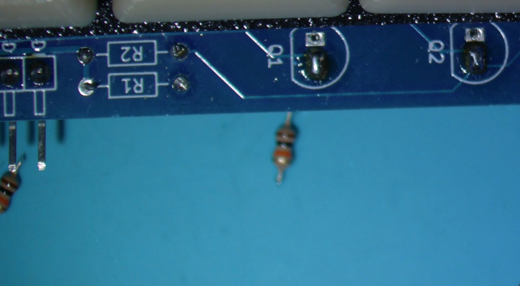
All you need to do is clip-off the 2x resistors, and the 2x 2N7000 MOSFETs. Then, you simply need to short the MOSFET pads that are closest to the board edge, such that the AVR Port F0 and F1 pins are now directly connected to the PS/2 connector.
Below is how the modification looks, on my v1.1 Keyboard PCB, that I’m currently using.
You should, of course, find all the resources on the DigicoolThings github repository.
Have fun!