
A few years ago, when I was re-discovering my original digital electronics design and breadboard prototyping background, I decided there was a need for a better LED indicator solution.
On first look, the “8-bit LED Thing” is a breadboard friendly 8-bit LED Bar display in a wider 16 pin Dual In-Line package.
But, the secret behind the “8-bit LED Thing” is that it actually contains the brains of a tiny microcontroller, making it a little smarter than your average LED Bar Display.
Join me as I introduce, then program & test the “8-bit LED Thing”. If you’d like one (or a few), please visit my Tindie Store.
Introduction
As most enthusiasts know, it’s quite common to hook-up LED’s to your digital or microprocessor based creations, to easily see the status at key points within your circuit.
Often, Dual In-Line LED Bar displays are used, for displaying the state of parallel data and address Bus’s, or even individual register contents.
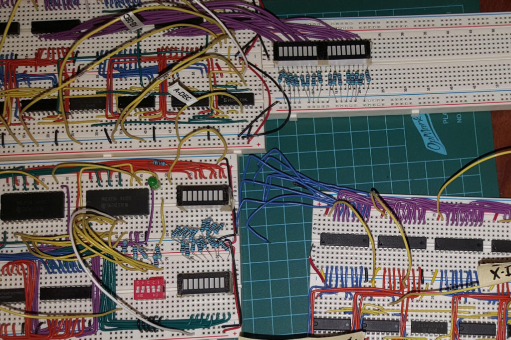
Now, although we love flashing lights and enjoy plenty of digital signal & register content visibility, there are a couple of problems with doing this.
Firstly, it seems quite common to simply hook-up an LED to a signal line, which we wish to monitor, via a current limiting resistor.
This, unfortunately, has the effect of significantly loading the signal that we are monitoring, quite often beyond the datasheet’s maximum source or sink current specification.
In addition, if you add a number of LEDs to your creation, you can significantly add to your project’s overall power consumption, also creating un-planned voltage-drops across your breadboard’s power feed wiring.
Secondly, hooking-up multiple LED’s and current limiting resistors, onto your circuit, can be quite a tedious process, with all of the resistors and hook-up wires needed, just to monitor a multi-bit bus or register.
This is where the Digicool Things “8-bit LED Thing” comes to the rescue. It solves all of these issues, along with adding some cool additional capabilities.
What Does the “8-bit LED Thing” Do?
On first look, the 8-bit LED Thing is a breadboard friendly 8-bit LED Bar display in a wider 16 pin Dual In-Line package.
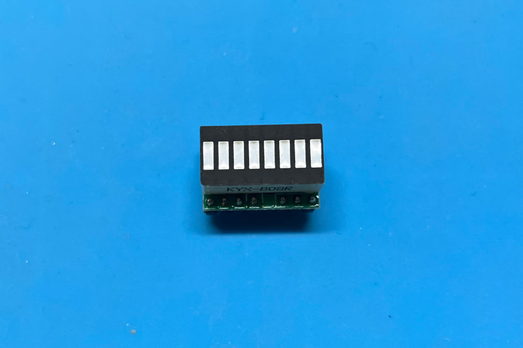
It is the same length as a Dual In-Line 16 pin IC package (0.1″ pitch), and 0.5″ wide (instead of 0.3″). So, they’re breadboard friendly. You can even place them end-to-end on your breadboard, to make 16-bit, or wider, LED Bar displays.
You might say: Huh? Why don’t I just use a regular Dual-In-Line 16 pin 8 LED Bar display?
Well, if you did, you would then need 8 current limiting resistors, additional wiring, and face the signal loading and other issues I’ve just discussed!
The secret behind the 8-bit LED Thing is that it actually contains the brains of a tiny microcontroller, making it a little smarter than your average LED Bar Display.
Firstly, to use it for displaying the status of up to 8 digital signals, you only need to connect up the two power pins. That is, Ground and your project’s 5V or 3.3V power line.
Then, up to 8 digital signals can be monitored just by connecting to any of the 8 pins along one side of The 8-bit LED Thing.
Now, apart from the ease of connection, and no need for current limiting resistors etc, the magic here is that each input presents as only a 1 micro-Amp load to the signal being monitored.
Yes, I said that correctly. Only 1 micro-Amp! Effectively, there is no load impact on the monitored signal!
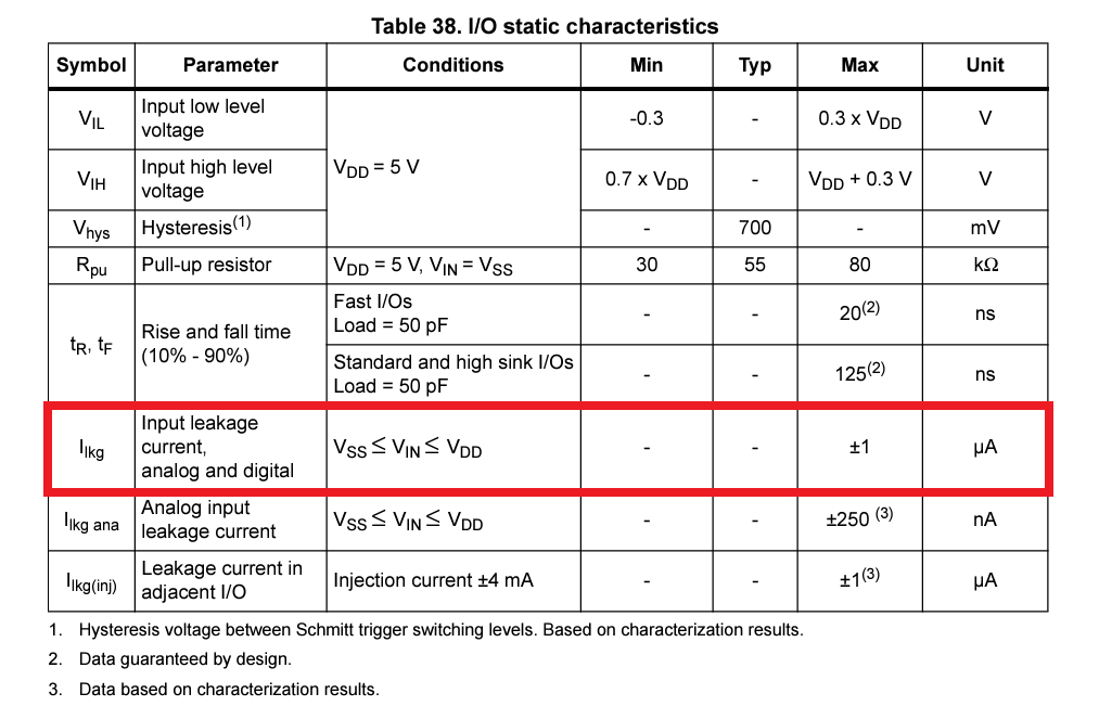
This is due to the fact that these sensing inputs are actually floating, so there is no pull-up or pull-down resistors adding load, or having any impact on your circuit.
However, because of this, do note that if any of the 8 digital level sensing inputs remain unused, then they should by tied to Ground.
In addition to this ease of use, and virtually no load on the signals being monitored, the Display is also efficient, as all the illuminated LED’s are charlieplexed.
Now this is only the start of the 8-bit LED Thing’s capabilities.
You see, this is just the 8-bit LED Thing operating in its default mode, and there are another 7 modes of operation.
8 Modes of Operation!
On the other side of the Display we have some more pins. You already know about the Ground and Power pins.
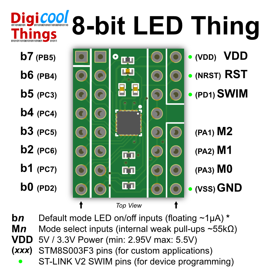
There are also 2 pins to support microcontroller programming.
In addition, there are also 3 mode control input pins (M0, M1 and M2). These mode pins have internal weak pull-ups enabled, so by default (with the pins not connected), we are in mode 7 (with all 3 mode pins pulled high).
So, mode 7 is the default 8 pin digital level signal monitoring mode.
By controlling the mode pins, we can switch to other modes, including a mode that even turns The 8-bit LED Thing into a Dice!
There are also various scanning display modes. All are explained on the laminated handout that comes with your “8-bit LED Thing”.
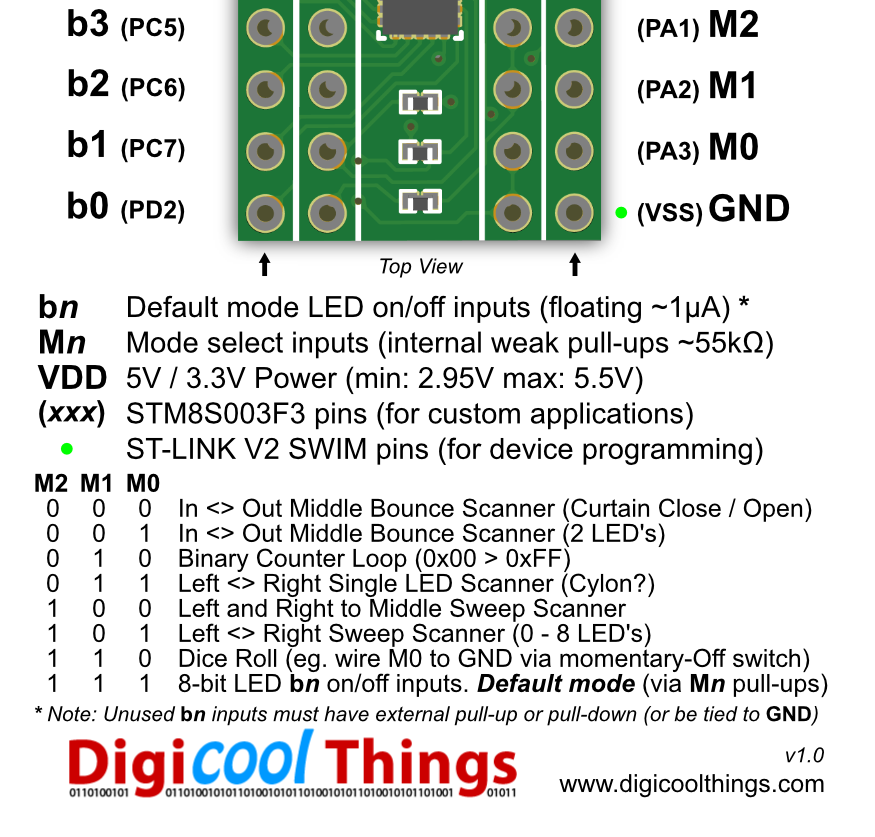
One common use would be to just pull the mode 1 pin (M1) low, to cause the LED Bar Display to be a sweep scanner (like the Knight Rider car of the 80’s TV series fame), for indicating periods when your project is in standby (for example). But, I’m sure you can use your own imagination!
Why am I Now Offering These?
I’ve actually been using a number of these 8-bit LED Things with my own projects, for several years now, without previously offering them as a solution for others to use.
You see, I designed and tweaked them before Covid hit. But, just when I was happy that they were complete, and ready for others to also use, Covid hit the global supply chain and the price of the microcontroller chips went up 10 fold!
Recently, I revisited making another batch, and I found that the component prices had since come back down, so the “8-bit LED Thing” was once again cost viable to offer, for other users to have as much fun with, as I’ve had.
As an aside, the “8-bit LED Thing” also made a fun design project, as they also represent the physically smallest microcontroller project that I’ve ever made.
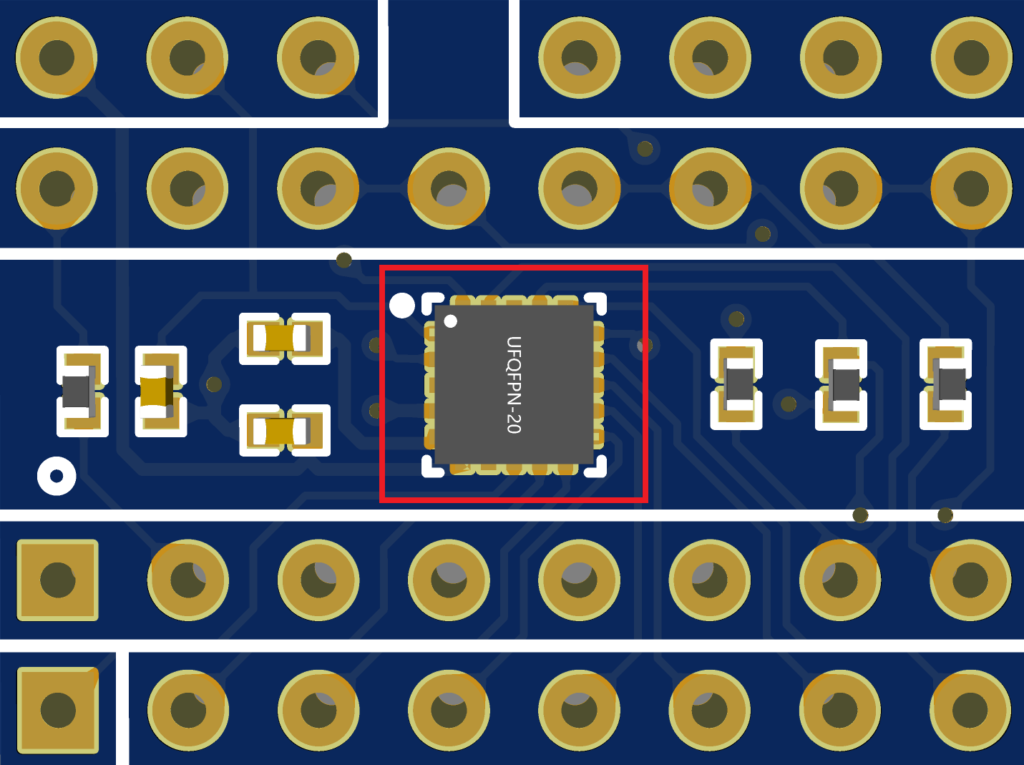
You can also consider the 8-bit LED Thing as simply a tiny STM8 microcontroller board, which you could also program for your own projects.
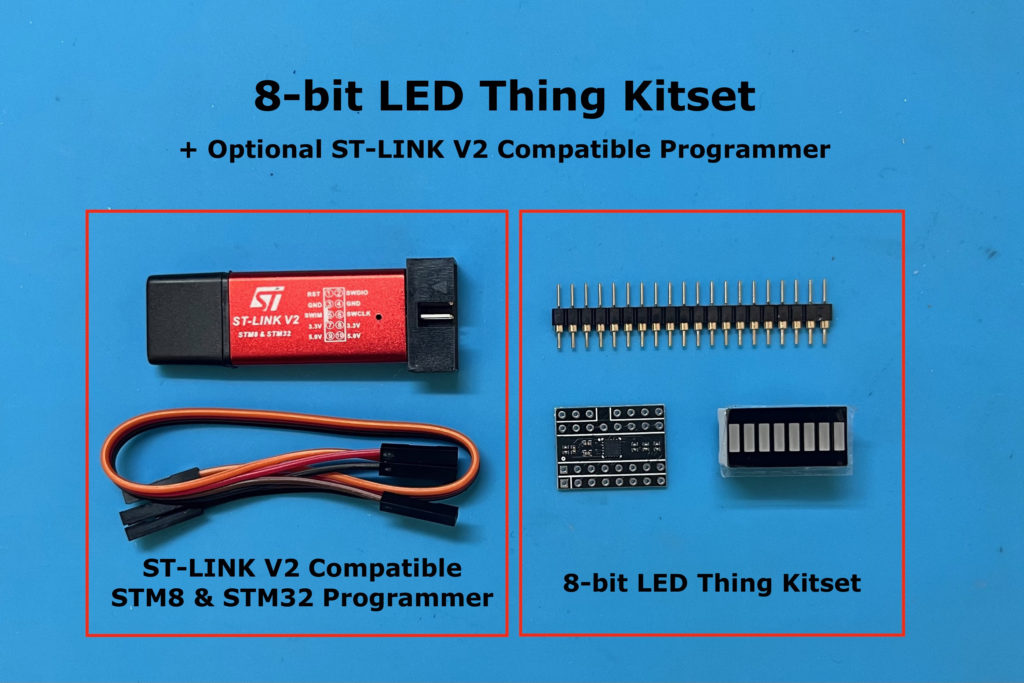
As such, I’ve decided to offer these in Kitset form, so you have the choice of using the bare MCU board, for your own use, or you can simply solder on the supplied LED Bar Display and the gold plated round-pin header strips, to complete your own 8-bit LED Thing.
I’ve also added an “Assembled” option, where I can assemble them for you, for a small fee.
I’ve managed to now make these available on my Tindie Store, and because it’s common to use multiple of them on your breadboard projects (I know I do), I’m offering a 4-up price. So, you can have 4 for a reduced bundle price.
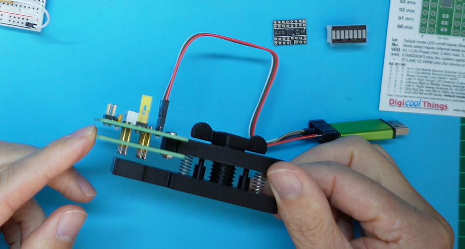
For fun, I thought I’d also show you the testing jig that I made, to allow me to program and fully test each PCB, prior to shipping, or before the final LED Bar display + header pin assembly.
Re-Programming The Microcontroller
To program the microcontroller you can simply use a ST-Link V2 USB Programmer, which is connected to the board with just 4 wires.
These are Ground, Power, Reset, and the ST single-pin SWIM interface. SWIM stands for Single Wire Interface Module.
If you don’t already have a ST-Link V2 Programmer, and want one to play around with programming the microcontroller yourself, I’m offering as an option, the same ST-Link V2 compatible USB Programmer that I’m using, so you can get one with your 8-bit LED Thing from my Tindie Store.
My 8-bit LED Thing Programmer and Tester jig
Okay, so here is my 8-bit LED Thing Programmer and Tester jig.
I first made a 3D printed design, inspired by the clip based pogo-pin programmers , which I saw available online.
But, after finalising the design, I decided I wasn’t happy with that approach.
You see, as it is a clip based design, with just 1 spring, the pogo-pins do not remain perpendicular as you open and close the clip. This is not ideal.
So, I went about making the two-spring design, that would nicely raise and lower the pins in a constantly perpendicular fashion.
I was also initially dreaming up a lever mechanism, for raising and lowering the test pins, but then I thought it would be much easier to simply use a thread and wing-nut.
The good thing is that this 3D printed testing jig design has then formed the design basis for several different product testers.
I even use an “8-bit LED Thing” on my tester for my TL866 EPROM Adapter PCB’s!
For the Jig design, the top part is identical on all of my testers, and the bottom is simply customised to match the PCB outline of the device to be tested.
Using the PCB outline for the base shape makes it very easy to line-up each PCB for testing.
The design also means, it is very easy to correctly assemble the tester’s pogo pins.
I simply need to bolt the new tester PCB’s in place on the top piece. Then insert the pogo-pins through their PCB mounting holes. And then, with the tester tightened down, the free pogo-pins nicely drop against the PCB outline base, on the bottom piece.
It’s then simply a case of soldering the top of the pins to the tester PCB, and they are automatically in the perfect position to allow the PCB thickness, of the PCB being tested, to compress the pogo-pins, on insertion.
Be sure to watch the video (linked above) for a full demonstration of programming and testing an “8-bit LED Thing” board with the testing jig.
What You Get
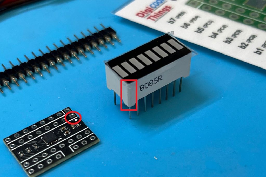
So, in summary, the 3 components of the Kitset version are:
- The surface mount device, assembled, programmed, and tested microcontroller board.
- A 16 pin 8 LED Bar Display.
- And, a 20 pin gold plated round pin header strip, for cutting into the 8 pin, 4 pin and 3 pin strips needed for final assembly.
To assemble, you simply need to first solder in the LED Bar Display, noting that pin 1, as indicated on the PCB, is the bevelled corner of the LED display.
Then, just solder on the header strips to create your completed “8-bit LED Thing”, ready to light up your projects, with no other parts or current limiting resistors needed.
If you’d like one, or a few, please visit my Tindie Store.
Resources, including the Firmware for programming an “8-bit LED Thing”, and a fullsize Handout png can be found on the GitHub project repository: https://github.com/DigicoolThings/8-bit_LED_Thing
I hope you have as much fun with the “8-bit LED Thing”, as I have!
Follow-Up: Kitset Assembly Guide & Tips
I’ve since created a follow-up post / video, which provides a walk-through of Kitset Assemble, together with assembly tips.
This is highly recommended viewing, before assembling your “8-bit LED Thing” Kitset!
You can find this here: 8-bit LED Thing – Kitset Assembly Guide & Tips!