
As a follow-up to my previous post / video, where I introduced the “8-bit LED Thing”, I thought it would be helpful to demonstrate Kitset Assembly.
Join me as I walk-through the assembly of an “8-bit LED Thing” kitset, and hopefully also provide a few helpful tips to ensure a successful assembly process.
First-off, assembly really is quite straight-forward. It just involves some simple TH (Through-Hole) soldering.
Don’t worry about the SMDs (Surface Mount Devices). The tiny microcontroller board is all pre-Assembled, pre-Programmed, and pre-Tested!
I figured that most people wouldn’t want to try soldering the SMDs anyway, as the microcontroller itself is a tiny 3mm square QFN package, and the other components are 0402.
i.e. Very small, and not the sort of thing that most hobbyists would want to even try to assemble, at least without specialist equipment!
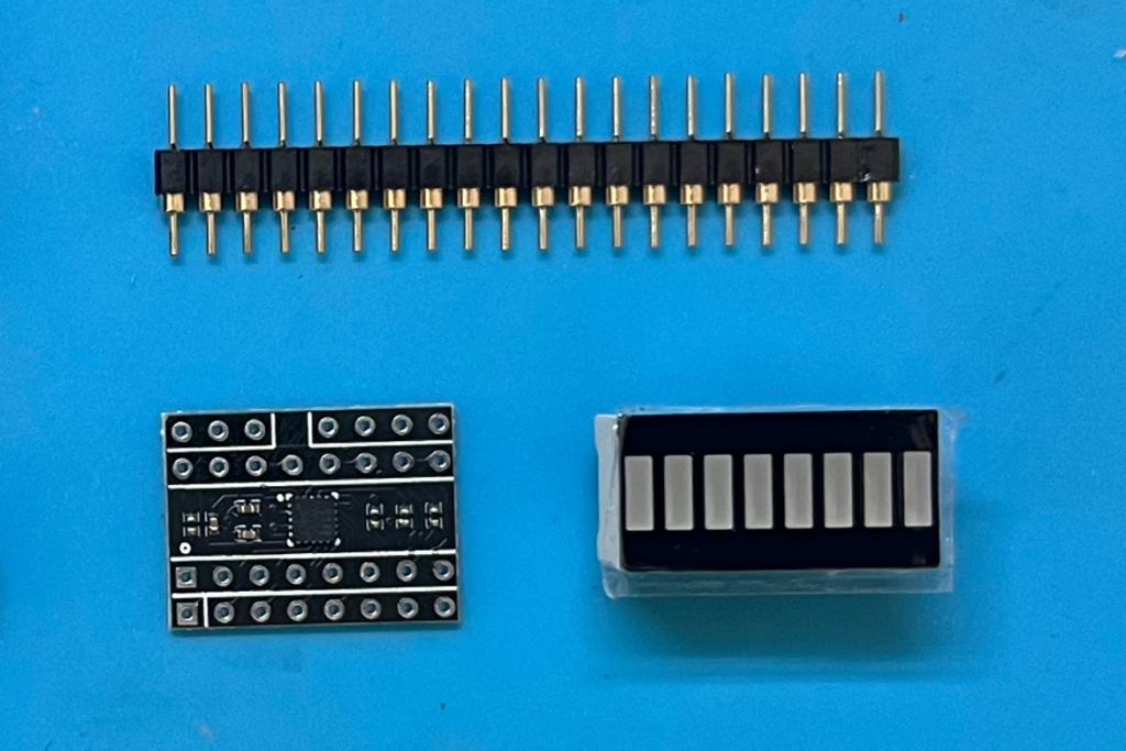
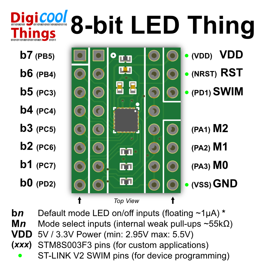
So, the “8-bit LED Thing” Kitset comprises of a fully assembled, programmed, and tested microcontroller board, a 16-pin Dual In-Line LED Bar display, and a 20 pin round-pin gold-plated header strip.
Therefore, each Kitset comprises of just these 3 components.
The reason I chose to offer the “8-bit LED Thing” in Kitset form, is two-fold.
Firstly, some enthusiasts might want to use the tiny microcontroller board for other project purposes, and therefore may not want to solder on the LED Bar display. Note that all microcontroller port pins are available at the microcontroller board solder pads.
Secondly, as the “8-bit LED Thing” is targeted at fellow electronic enthusiasts, it’s highly likely you may want to assemble it yourself.
But, just in case, I do offer the option of having me assemble the Kitset for you (for a small fee), if you prefer.
Okay, with that explained let’s dive in.
Apart from the Kitset itself, you’ll also need your soldering iron and side-cutters.
In addition, I also recommend a breadboard, and (optionally), a power supply and a current limiting resistor.
If you’re using a 5V or 3.3V power supply, then perhaps a 220 ohm or 270 ohm resistor would be ideal.
Note that the “8-bit LED Thing” is rated for a 2.95V to 5.5V power supply range!
Now, my suggestion of a power supply and current limiting resistor, is to allow checking the LED Bar Display, before you solder it onto the microcontroller board.
Although this shouldn’t be necessary, it is generally a good idea to double check and be safe rather than sorry.
You see, if you were to inadvertently solder the LED Bar Graph display the wrong way around, or if you were to discover one of the LED’s wasn’t working, then desoldering the 16-pin LED Display would be challenging and also (quite possibly), damaging to the microcontroller board.
Okay, first-off is to identify the orientation of the LED Bar Display.
Unlike a DIL packaged IC, which usually has a really obvious dimple or notch to indicate the Pin-1 end of the IC, the LED Bar Display just has a subtle bevel on one corner edge of the display.
Here’s how it looks close-up…
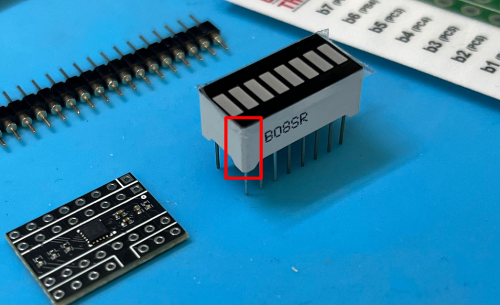
You can usually either feel the bevel with your finger (comparing to the feel of the other corner edges), or you might want to use a magnifier.
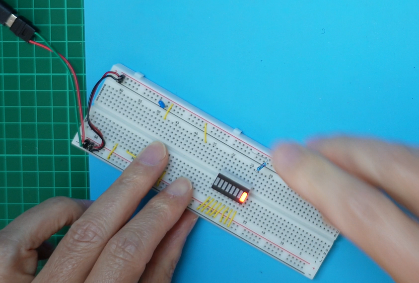
Once you have located Pin-1, you can insert the LED Bar Graph into your breadboard.
We want to jumper all of the Pin-1 side to your ground rail (so pins 1 to 8 are all shorted together and connected to ground), with the pins on the other side of the display (pins 9 – 16), not connected!
As you’ve probably guessed, this is because the Pin-1 marked side of the microcontroller board is designed for the Cathode ends of the LED Bar Display’s 8 LED’s.
The other side (pins 9 to 16), are for the Anode ends of the 8 LED’s.
With power applied, we then want to connect each of the LED Anode pins (i.e. Typically Pins 9 to 16), one at a time, through the current limiting resistor to your power rail.
All going well, we should then see each LED illuminate!
If your LEDs don’t illuminate, chances are you have mis-identified Pin-1 of the LED Display. Or, you forgot to turn on your power supply! 🙂
There is another (although currently unlikely), possibility. That is, that the LED Bar Display is reverse wired! To check for this, simply rotate your LED Bar Display 180 degrees, so you now have pins 9 to 16 connected to ground.
Assuming you’ve now successfully tested your LED Bar Graph display, and therefore are confident it is all working and you have correctly identified Pin-1 (or, more correctly, the Cathode side of the display), then you are ready for your “8-bit LED Thing” assembly.
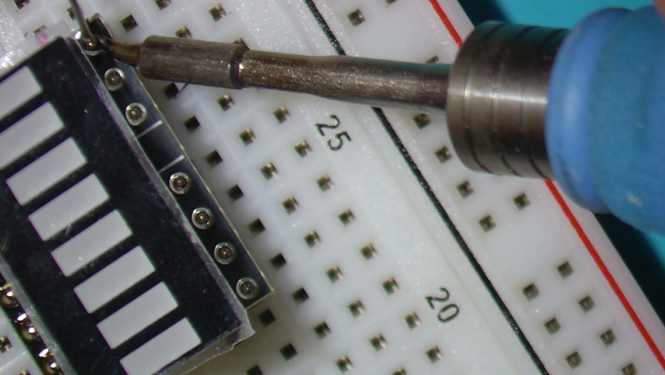
The first step is to solder in the LED Bar Graph, noting the Pin-1 identifier on the PCB, which indicates the Cathode side of the LED Bar Display.
The LED Bar Graph essentially fits over the tiny microcontroller, and the other tiny SMD components, effectively hiding them from sight.
I just emphasis this, to make sure you don’t assemble the board upside down!
Okay, with the LED Bar Display inserted and firmly bedded against the PCB, lets get it soldered.
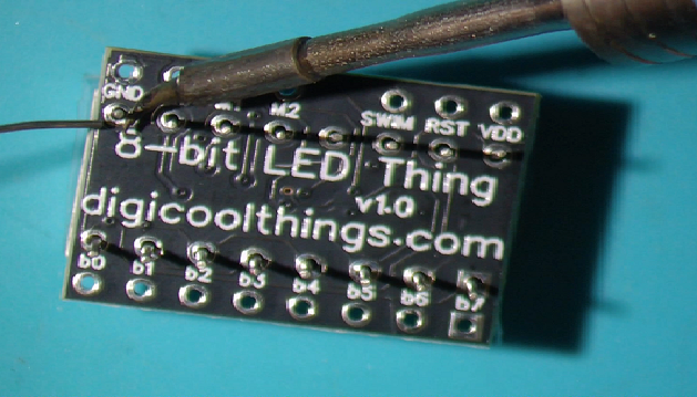
Once soldered, you can then snip-off the excess leads with your side-cutters.
Next, we want to cut an 8-pin, a 4-pin, and a 3-pin length from the supplied 20-pin round-pin header strip. This should leave you with a 5-pin strip, which is surplus / spare.
Then, back to your breadboard.
With breadboard power disconnected (and perhaps wise now to remove your power jumper wires), as we’re just using the breadboard to assist with assembly, first insert the longer pins of the header-strips into your breadboard like so…
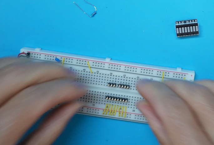
You should have the 8-pin strip and the 3 & 4 pin strips inserted with a 0.5″ spacing between them, to replicate the remaining edge holes on the microcontroller board.
With the longer pin sides of the header strips inserted into the breadboard, you should now be able to just drop the microcontroller board, with it’s LED Display, in-place, onto the pins.
We are now ready to solder the pins in-place, knowing that the pins are all held nicely straight, by the breadboard.
And, with that done, we’ve completed assembly of our “8-bit LED Thing” Kitset.
Pretty easy!
Oh yeah… Don’t forget, you might want to also remove the protective film from the front of the LED Display (you can see it in the photo above), for a professional finish!
Lastly, for some LED lighting enjoyment, and to check your assembly, I’d suggest first jumpering the M1 Mode pin to ground. Then, also connect the corner ground pin (Pin-8) to your ground rail, and the corner VDD pin (Pin 16), to your 5V or 3.3V power.
Then, after a final check (as we should always of course do), you’re now ready to apply 5V or 3.3V power.
Apply power, and all going well you should be immediately rewarded with a Knight Rider LED Scanning display!
Well, hopefully the above has demonstrated how easy it is to assemble an “8-bit LED Thing”, and has also (hopefully), provided a couple of useful tips to ensure successful assembly, first time!