Page 2 of 3

Re: Struggling with EEPROM addressing ...

Posted: Fri Jul 12, 2024 11:22 am
by Michael
Progress: address LEDs look good for function call now (so EEPROM and SRAM working). Not reliable in terms of startups (probably the test rig).

The only thing I did was properly clean the solder side of the board. Also, too many LEDs directly on the 6502 on the address bus seemed less reliable.

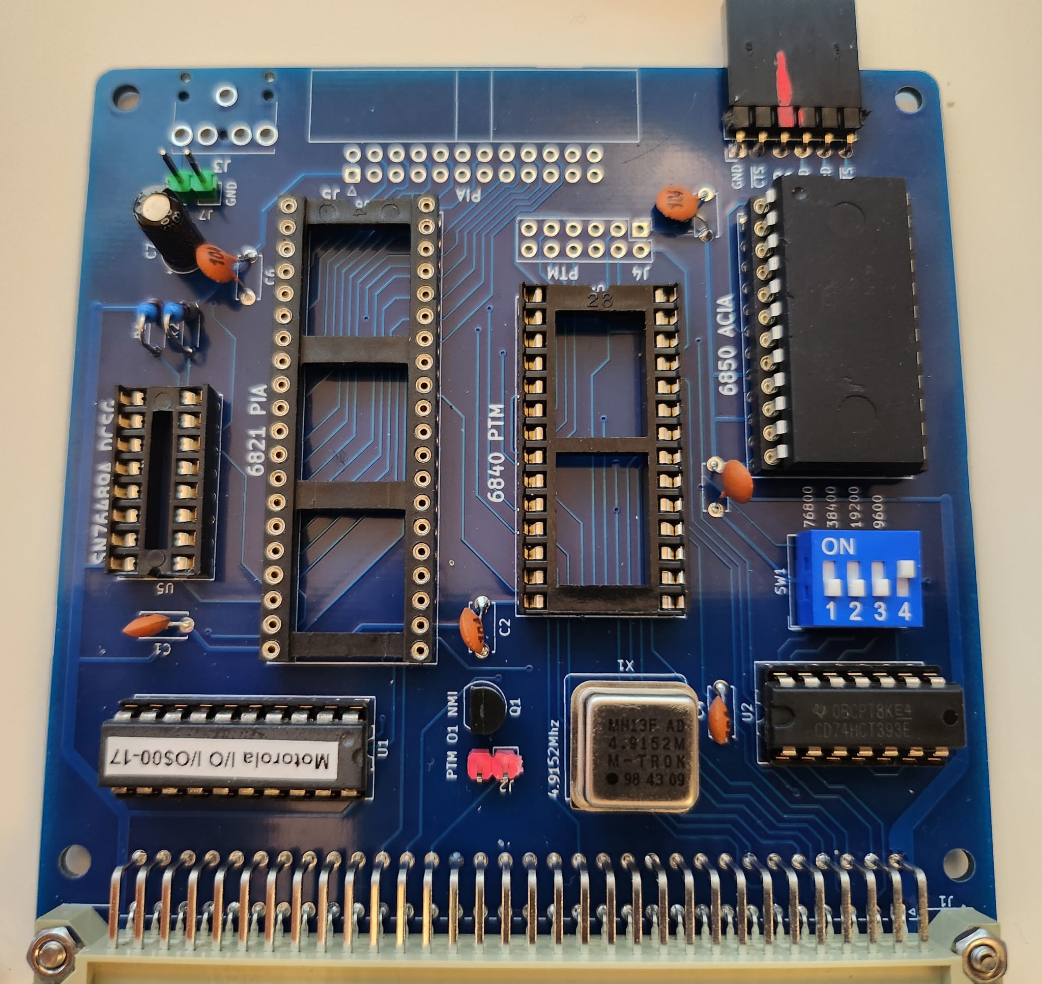
Next: tried to get the ACIA "hello world" working. Depopulated the I/O card to what I assume is the minimum for just using the ACIA.

Spot anything obvious? Running at 9600 for now.
Image

My version of hello world:

Code: Select all

// constant data

0xF000  0x5C 0x72 0x5C 0x6E 0x48 0x65 0x6C 0x6C  0x6F 0x20 0x36 0x35 0x30 0x32 0x20 0x57  // \r\nHello.6502.W
0xF010  0x6F 0x72 0x6C 0x64 0x21 0x5C 0x72 0x5C  0x6E 0x00                                // orld!\r\n.

// /Source/Testing/Minimal/hello.asm:33
// ####  HelloMECB.Hopper()  ####                                               0x0000

0xF01A  0xD8            CLD                     
0xF01B  0xA2 0xFF       LDX # 0xFF              
0xF01D  0x9A            TXS                     
0xF01E  0x78            SEI                     // SEI           Disable Interrupts  hello.asm:35
0xF01F  0xD8            CLD                     // CLD           Clear Decimal flag (Binary mode)
0xF020  0xA2 0xFF       LDX # 0xFF              // LDX # 0xFF    Initialise Stack pointer ($01FF)
0xF022  0x9A            TXS                     // TXS                               hello.asm:38
0xF023  0xA9 0x03       LDA # 0x03              // LDA # 0x03                        hello.asm:41
0xF025  0x8D 0x08 0xE0  STA 0xE008              // STA ACIA              Reset ACIA  hello.asm:42
0xF028  0xA9 0x51       LDA # 0x51              // LDA # 0b01010001    Receive interrupt disabled, Transmit interrupt disabled, 8 bits, 2 stop bits, no parity, /16 clock,
0xF02A  0x8D 0x08 0xE0  STA 0xE008              // STA ACIA                          hello.asm:46
0xF02D  0xA2 0x00       LDX # 0                 // LDX # 0x00           Initialise character offset pointer
0xF02F  0xA9 0x02       LDA # 0x02              // LDA #0x02               Transmit Data Register Empty flag mask
0xF031  0x2C 0x08 0xE0  BIT 0xE008              // BIT ACIA                Is Transmit Data Register Empty?
0xF034  0xF0 0x03       BEQ 0xF039 (+3)         // if (Z) { continue; }    Loop if not empty
0xF036  0x80 0x04       BRA 0xF03C (+4)         
0xF038  0xEA            NOP                     
0xF039  0x80 0xF4       BRA 0xF02F (-12)        
0xF03B  0xEA            NOP                     
0xF03C  0xBD 0x00 0xF0  LDA 0xF000,X            // LDA Hello, X            Get next character to send
0xF03F  0xF0 0x03       BEQ 0xF044 (+3)         // if (Z) { break;    }    If it's the zero string terminator, we're done!
0xF041  0x80 0x04       BRA 0xF047 (+4)         
0xF043  0xEA            NOP                     
0xF044  0x80 0x08       BRA 0xF04E (+8)         
0xF046  0xEA            NOP                     
0xF047  0x8D 0x09 0xE0  STA 0xE009              // STA ACIAtr             Send the character
0xF04A  0xE8            INX                     // INX                     Increment character offset pointer
0xF04B  0x80 0xE2       BRA 0xF02F (-30)        // }                                 hello.asm:61
0xF04D  0xEA            NOP                     
0xF04E  0x80 0xFE       BRA 0xF04E (-2)         // loop {}                     Done, so just Loop Forever!
0xF050  0xEA            NOP                     
0xF051  0xDB            STP                     // }                                 hello.asm:63

// /Source/Testing/Minimal/hello.asm:27
// ####  HelloMECB.IRQ()  ####                                                  0x0001

0xF052  0x40            RTI                     // }                                 hello.asm:28

// /Source/Testing/Minimal/hello.asm:30
// ####  HelloMECB.NMI()  ####                                                  0x0002

0xF053  0x40            RTI                     // }                                 hello.asm:31

0xFFFA 0xF053 // NMI vector
0xFFFC 0xF01A // Reset vector
0xFFFE 0xF052 // IRQ vector


Re: Struggling with EEPROM addressing ...

Posted: Fri Jul 12, 2024 7:02 pm
by Editor
Quick check... Have you grounded the CTS pin? The 6850 ACIA needs this input grounded (low), if hardware handshaking isn't being used.

The LED's on the Address Bus are possibly overloading the total output driver capability of the 6502 processor?
That'd be solved with a couple of 8-bit LED Things, with their minimal 1 microAmp signal loading. ;)

Re: Struggling with EEPROM addressing ...

Posted: Fri Jul 12, 2024 11:14 pm
by epaell
Just a thought, as this always catches me unaware and you may have already checked this ... but is there any possibility the RX/TX are reversed with whatever device you have connected? I always struggle with this and it is never clear to me from what perspective these are labelled on the various devices. Curiously, I don't have CTS grounded and it seems to work ... now I'm wondering why? 🤔

I'm assuming you have your processor board set to $E0 for the I/O. For what it's worth my board looks similar to yours (everything in the same orientation). The only difference is that I threw in a 7.3728 MHz crystal and set the DIP switch to plaid mode (switch "1" on). Here is my board - I have an extra cable to provide power to the DB9 interface.

Image

Re: Struggling with EEPROM addressing ...

Posted: Fri Jul 12, 2024 11:49 pm
by Editor
epaell wrote: ↑Fri Jul 12, 2024 11:14 pm Just a thought, as this always catches me unaware and you may have already checked this ... but is there any possibility the RX/TX are reversed with whatever device you have connected? I always struggle with this and it is never clear to me from what perspective these are labelled on the various devices.
As per my interpretation of the FTDI connector standard, the Tx on the I/O Card goes to the 6850 Tx output pin, and the Rx goes to the 6850 Rx input pin. Likewise, the RTS and CTS pins. i.e. Nothing is reversed.

Normally you'd connect your terminal's Tx connection to the computer's Rx pin etc. i.e. Cross-over is in the cable / connection.
Unless your RS232 interface already crosses-over the connections on it's board?
Yes, totally confusing!
epaell wrote: ↑Fri Jul 12, 2024 11:14 pm Curiously, I don't have CTS grounded and it seems to work ... now I'm wondering why? 🤔
I'd say you are lucky. The disconnected input must be floating low.
If not using RTS/CTS handshaking, I'd definately recommend that the CTS input be tied to ground.
epaell wrote: ↑Fri Jul 12, 2024 11:14 pm I'm assuming you have your processor board set to $E0 for the I/O. For what it's worth my board looks similar to yours (everything in the same orientation). The only difference is that I threw in a 7.3728 MHz crystal and set the DIP switch to plaid mode (switch "1" on).
I typically have been asigning the I/O space to the bottom of ROM. So, with the 56K / 8K PLD, I usually have the I/O bank at $E0xx, just stealing 256 bytes from the bottom of the ROM address space.
This also helps with ASSIST09 on the 6809, as by default, the monitor is configured for top of RAM at $DFFF. It's an offset from the start of ROM code, which is the top 2KB by default ($F800).

So, you're running at 115,200 baud. Nice, but also pretty fast for running with no handshake on a slower processor! You are likely to have receiver overruns, when downloading code etc. I usualy just run at 38,400. Just a thought. :thinking:

Re: Struggling with EEPROM addressing ...

Posted: Sat Jul 13, 2024 1:34 am
by epaell
I'd say you are lucky. The disconnected input must be floating low.
Quite possibly, I did have a different device previously that had RTS and CTS (and I had those connected correctly) but connected via a USB interface whereas I actually wanted something that connects via a standard DB9 serial connector so that I could connect to a computer or a serial terminal. However, the new device I connected only had Rx and Tx so I forgot to set up the CTS level correctly. I'll connect that now just in case.
You are likely to have receiver overruns
I've mainly been testing with the 6309 (with fairly large downloads when testing things like BASIC) but it has been pretty good. I'd have to admit that I may still have delays in my transmit software at the end of each line (to give the 6309 time to breath and process the line it has received - which caused issues even at much lower speeds) but now I'm curious to see how much it can receive in a stream before things collapse into a quivering heap. If I get a chance I may try write a simple bit of software to just continually read from the ACIA (with minimal processing, perhaps just dumping into a memory buffer for subsequent checking) just to see if pure reception can keep up at the full rate and possibly also test with the w65c02s (which I'm currently running at a measly 2 MHz but I believe it should be able to go much higher than that).

I'll also explain that the reason for adding 115200 baud was just pure laziness on my behalf i.e. the terminal software I use on the Mac (minicom) defaults to this baudrate as too does the VGA Terminal that I threw together - so it saves me having to change anything when I plug things together 😀

Re: Struggling with EEPROM addressing ...

Posted: Sat Jul 13, 2024 6:49 am
by Editor
Michael wrote: ↑Fri Jul 12, 2024 6:36 am PCB:
- most important : the 'green' / cheap ZIF sockets have bigger pins that you allot for the EEPROM (can't be inserted) - if there is a revision, use footprint with bigger holes for the EEPROM
Another great catch!

Fortunately, on the new Prototype with PLD Card, the PLD has 1.0mm pad holes, as does the MECB Template's PLD.

However, for some reason I seemed to have missed this on the other Cards.
So, today, I went through all MECB Cards and updated them so that all PLD and ROM footprints have 1mm pad holes (instead of 0.8mm).

I didn't go as far as incrementing the board revision numbers, as I was debating whther this justified an increment or not. However, it does mean that next time I re-order a Card, any new card stock will have these 1.0mm holes (instead of 0.8mm).
EDIT (14 July): After re-thinking this, I am now progressively updating the minor board revision number (and updating gerbers), for the Cards that had a change to the PLD and ROM footprints (to allow ZIP sockets hole size). This is of course a minor functional difference (at least for those who want to use ZIF sockets!). Whereas, for Cards with only silkscreen changes, I have not updated the version number.

Michael wrote: ↑Fri Jul 12, 2024 6:36 am Silkscreen:
- I prefer to clearly mark the negative side for electrolytic caps (since that is the side marked on the cap) - holes were a bit tight too
- I know there is a square corner but probably better to put the label on the 'up' side of the can oscillators (same orientation as text on cans)
I've fixed the footprints for the Electrolytic Caps, including a '-' on the -ve side, and also ensuring the -ve side is a silkscreen filled area.
The Backplane electrolytics were the worst / most confusing.

For the Oscillators, I've added a clear '1' next to pin-1, as I wasn't sure what you meant by: "on the 'up' side"?
Also, the text on the oscilator cans might vary orientation with manufacturer?

Hopefully some progress towards increased clarity! :geek:

Re: Struggling with EEPROM addressing ...

Posted: Sat Jul 13, 2024 7:32 am
by epaell
Right, so ASSIST09 definitely has overruns at full speed ... although my test code (which buffered the received data) didn't run into problems (at least until I introduced a delay in my character receive subroutine that looped around 24 times twiddling its digits - then it had an overrun ... though, apparently 23 twiddles is fine). So I think the processor is fine but a relatively tight loop is needed to work at full transfer speed.

Re: Struggling with EEPROM addressing ...

Posted: Sat Jul 13, 2024 7:46 am
by epaell
Now I recalled the other issue I had - apparently the software I'm using doesn't support 76800 baud. 38400 is OK though. And now that I think about it, this actually faster than 115200 baud because to get that to work with ASSIST09 when loading software I need to introduce a character delay of 1 mS in the terminal (it doesn't allow any shorter delays) - which effectively limits the transfer to 8000 baud (at most) anyway. Sigh, perhaps I'll be less lazy and work with 38400 after all.

Re: Struggling with EEPROM addressing ...

Posted: Sat Jul 13, 2024 2:44 pm
by Michael
Editor wrote: ↑Fri Jul 12, 2024 7:02 pm Quick check... Have you grounded the CTS pin? The 6850 ACIA needs this input grounded (low), if hardware handshaking isn't being used.
You could be onto something. Adding that to my checklist for when I return to the scene of the crime.

Re: Struggling with EEPROM addressing ...

Posted: Sat Jul 13, 2024 2:50 pm
by Michael
epaell wrote: ↑Fri Jul 12, 2024 11:14 pm Just a thought, as this always catches me unaware and you may have already checked this ... but is there any possibility the RX/TX are reversed with whatever device you have connected? I always struggle with this and it is never clear to me from what perspective these are labelled on the various devices.
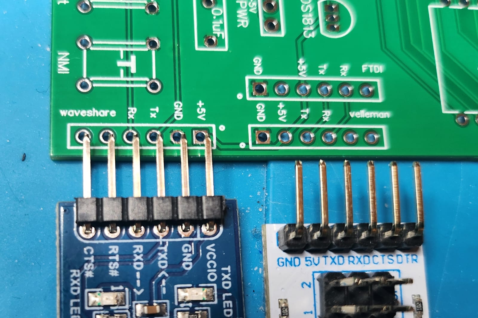
I'm using the same FTDI connector (not separate jumpers) that I use on my Hopper 6502 SBC which also has the 6850 and I used a multimeter to check the header pins against the 6850 pins to make sure they are the same as on my other board.

But ... you made me doubt myself so I checked again and you were spot on the money!! :D

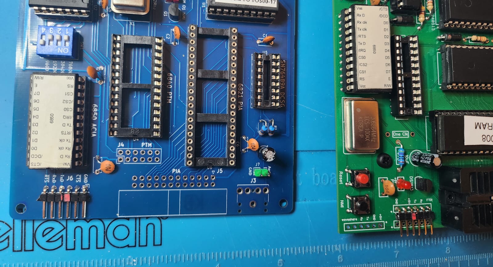
The Tx and Rx on my board (the green one) correspond to the silk screen markings on the waveshare and velleman FTDI devices (and the pinout of the ftdichip.come cable connector.
The ones on the MECB I/O card correspond to the pins on the 6850!! (the opposite)

Image
Image