
In the past I've used the WD 65C22 VIA to provide a free running timer that fires an IRQ ever n microseconds.
I'm hoping to do the same with the 6840 on the MECB I/O Board.
Any pointers toward some clear 6502 / 6809 sample code that does just this?
- initialization
- responding to the IRQ
My current failing attempt to initialize can be found here: (yes, the code for the 6840 is in the same file as the 6821)
https://github.com/sillycowvalley/Hoppe ... 21.asm#L68
Motorola 6840 Programmable Timer Module (PTM)

Re: Motorola 6840 Programmable Timer Module (PTM)
I just found a rather tasty pdf you might like 
Re: Motorola 6840 Programmable Timer Module (PTM)
My latest (non working) attempt for review. The ISR is never triggered.
(complete source here: https://github.com/sillycowvalley/Hoppe ... 21.asm#L91)
(complete source here: https://github.com/sillycowvalley/Hoppe ... 21.asm#L91)
Code: Select all
// Motorola 6840 PTM (Programmable Timer Module)
    const uint TCR                  = 0xF000;  // Write: Timer Control Registers 1 & 3   Read: NOP
    const uint TCSR2                = 0xF001;  // Write: Control Register 2              Read: Status Register (least significant bit selects TCR as TCSR1 or TCSR3)
    const uint TIMER1_MSB           = 0xF002;  // Write: MSB Buffer Register             Read: Timer 1 Counter
    const uint TIMER1_LSB           = 0xF003;  // Write: Timer #1 Latches                Read: LSB Buffer Register
    const uint TIMER2_MSB           = 0xF004;  // Write: MSB Buffer Register             Read: Timer 1 Counter
    const uint TIMER2_LSB           = 0xF005;  // Write: Timer #1 Latches                Read: LSB Buffer Register
    const uint TIMER3_MSB           = 0xF006;  // Write: MSB Buffer Register             Read: Timer 1 Counter
    const uint TIMER3_LSB           = 0xF007;  // Write: Timer #1 Latches                Read: LSB Buffer Register

isr()
    {
        BIT TimerStatus
        if (MI) // IRQ by Timer 1, 2 or 3
        {
            PHA
            LDA TimerStatus
            AND # 0b00000001 // Timer 1 interrupt
            if (NZ)
            {
                // Read Timer 1 counter to clear interrupt
                LDA Timer1Counter
                INC  ZP.TICK0
                if (Z)
                {
                    INC  ZP.TICK1
                    if (Z)
                    {
                        INC  ZP.TICK2
                        if (Z)
                        {
                            INC  ZP.TICK3
                        }
                    }
                }
            }

            PLA
        }
    }

    sharedSamplesMicroSet()
    {
        // Motorola 6840 Timer

        // No prescaler:

        LDA # 0b00000001            // Select Timer 3 Control Register
        STA Timer2Control
        // CR30 = 0 - no prescaler
        LDA # 0b00000000
        STA Timer3Control           // Write to Timer 3 Control Register

        // Select Timer 1:

        LDA # 0b00000001            // Select Timer 1 Control Register
        STA Timer2Control
        //  CR10 = 1 all timers held in preset state (disabled)
        LDA # 0b00000001            // Disable all timers during configuration
        STA Timer1Control

        // Zero the tick counter
#ifdef CPU_65C02S
        STZ ZP.TICK0
        STZ ZP.TICK1
        STZ ZP.TICK2
        STZ ZP.TICK3
#else
        LDA #0
        STA ZP.TICK0
        STA ZP.TICK1
        STA ZP.TICK2
        STA ZP.TICK3
#endif

        // At a CPU clock of 1 mHz = 1000 cycles - 1 = 999 / 0x03E7 would give us a sample cycle of 1ms
#if defined(CPU_2MHZ) || defined(CPU_4MHZ) || defined(CPU_8MHZ)
        // x2
        ASL ZP.TOPL
        ROL ZP.TOPH
#endif
#if defined(CPU_4MHZ) || defined(CPU_8MHZ)
        // x4
        ASL ZP.TOPL
        ROL ZP.TOPH
#endif
#if defined(CPU_8MHZ)
        // x8
        ASL ZP.TOPL
        ROL ZP.TOPH
#endif
        // The timer counts down from n-1 to 0, including the 0 as part of the count
        // -1
        LDA ZP.TOPL
        if (Z)
        {
            DEC ZP.TOPH
        }
        DEC ZP.TOPL

        // CR10 = 0 - all timers are allowed to operate
        // CR21 = 0 - use external clock source
        // CR22 = 0 - normal 16 bit counting mode

        // CR23 = 0 - continuous mode (write to latches or reset causes initialization)
        // CR24 = 0
        // CR25 = 0

        // CR26 = 1 - interrupt flag enabled to IRQ
        // CR27 - 0 - output masked on output OX

        LDA # 0b01000000
        STA Timer1Control    // Write to Timer 1 Control Register


        // Write to latches to initialize:

        // Always write the MSB to the single MSB buffer register first:
        LDA ZP.TOPH          // Load MSB of 1000 cycles
        STA Timer1MSBBuffer  // Write to Timer 1 MSB register

        LDA ZP.TOPL          // Load LSB of 1000 cycles
        STA Timer1LSBLatch   // Write to Timer 1 LSB register

    }
Re: Motorola 6840 Programmable Timer Module (PTM)
After a lot of head-scratching (mainly me fighting with the 6840 documentation, fighting with how to do things with a 6502, and then fighting with SMON) I finally got something that works:
Note that I mainly used SMON to avoid having to write a ROM each time to test something ... but in some ways I could've avoided a lot of pain as I initially had my program inadvertently overlapping with memory space that SMON needed (silly mistake on my behalf) ... and then after fixing that found that SMON was pushing registers to the stack before calling the used interrupt service routine (something I was doing in my ISR but then not pulling off what SMON had pushed and so made a mess of the stack). Anyway, all that is fixed in the above.
The code sets up the 6840 to cause an interrupt after the countdown from some value (timer_LSB/timer_MSB); for each interrupt a 32-bit counter is incremented. The main loop simply reads the 32-bit counter and writes it to the terminal.
It's not exactly what you asked for but I hope that providing a somewhat working example can help to get your own version up and running. Hopefully just some of the values need some tweaking for your application.
Code: Select all
MECB_IO         EQU     $E000
;
; Motorola 6840 PTM (Programmable Timer Module)
;
PTM             EQU     MECB_IO
PTM_CR13        EQU     PTM         ; Write: Timer Control Registers 1 & 3   Read: NOP
PTM_SR          EQU     PTM+1
PTM_CR2         EQU     PTM+1       ; Write: Control Register 2              Read: Status Register (least significant bit selects TCR as TCSR1 or TCSR3)
;
PTM_T1MSB       EQU     PTM+2       ; Write: MSB Buffer Register             Read: Timer 1 Counter
PTM_T1LSB       EQU     PTM+3       ; Write: Timer #1 Latches                Read: LSB Buffer Register
;
PTM_T2MSB       EQU     PTM+4       ; Write: MSB Buffer Register             Read: Timer 1 Counter
PTM_T2LSB       EQU     PTM+5       ; Write: Timer #1 Latches                Read: LSB Buffer Register
;
PTM_T3MSB       EQU     PTM+6       ; Write: MSB Buffer Register             Read: Timer 1 Counter
PTM_T3LSB       EQU     PTM+7       ; Write: Timer #1 Latches                Read: LSB Buffer Register
;
; Motorola 6850 ACIA
;
ACIA            EQU     MECB_IO+$08 ; Location of ACIA
ACIA_STATUS     EQU     ACIA        ; Status
ACIA_CONTROL    EQU     ACIA        ; Control
ACIA_DATA       EQU     ACIA+1      ; Data
;
; SMON IQR
;
IRQ_LO          EQU     $0314         ; Vector: Hardware IRQ Interrupt Address Lo
IRQ_HI          EQU     $0315         ; Vector: Hardware IRQ Interrupt Address Hi
;
                ORG     $1000
;
start           ldx     #<isr       ; Set up IRQ vector in SMON
                stx     IRQ_LO
                ldx     #>isr
                stx     IRQ_HI
;
                lda     #$03        ; Initialise the ACIA
                sta     ACIA_CONTROL
                lda     #$15
                sta     ACIA_CONTROL
;
                lda     #'S'
                jsr     outch       ; Write an "S" to indicate program started
                jsr     ptm_init    ; Initialise the PTM
                cli                 ; Enable interrupts
loop            lda     #$0d
                jsr     outch
                lda     #$0a
                jsr     outch
                lda     #'0'        ; Write the current tick count
                jsr     outch
                lda     #'x'
                jsr     outch
                lda     tick3
                jsr     out2h
                lda     tick2
                jsr     out2h
                lda     tick1
                jsr     out2h
                lda     tick0
                jsr     out2h
                jmp     loop        ; Infinite loop
;
;
; Subroutine to initialise the PTM for continuous mode with interrupts generated by timer 1
;
ptm_init        lda     timer_MSB   ; Set up the countdown timer for timer 1
                sta     PTM_T1MSB   ; MSB must be written first!
                lda     timer_LSB
                sta     PTM_T1LSB
;
                lda     #$01        ; Preset all timers
                sta     PTM_CR2     ; Write to CR1
                lda     #$42        ; CRX6=1 (interrupt); CRX1=1 (enable clock)
                sta     PTM_CR13
                lda     #$00
                sta     PTM_CR2
                sta     tick0       ; Reset the tick counter
                sta     tick1
                sta     tick2
                sta     tick3
;
                lda     PTM_SR      ; Read the interrupt flag from the status register
;
;                lda     #$40
;                sta     PTM_CR13       ; enable interrupt and start timer
                rts
;
tick0           ds.b    1
tick1           ds.b    1
tick2           ds.b    1
tick3           ds.b    1
;
timer_LSB       dc.b    $00
timer_MSB       dc.b    $F0
;
isr             ;pha                 ; Note: Registers already pushed on stack by SMON
                ;txa
                ;pha
                ;tya
                ;pha
;
                lda     PTM_SR      ; Read the interrupt flag from the status register
                lda     PTM_T1MSB   ; clear interrupt flag
                lda     PTM_T1LSB
;
                clc                 ; Increment tick counter
                lda     tick0
                adc     #$01
                sta     tick0
                lda     tick1
                adc     #$00
                sta     tick1
                lda     tick2
                adc     #$00
                sta     tick2
                lda     tick3
                adc     #$00
                sta     tick3
;
                pla                 ; Restore registers that were previously pushed on stack by SMON
                tay
                pla
                tax
                pla
                rti
;
; write character to the ACIA, wait until ACIA is ready to transmit
; A, X and Y registers preserved
;
outch           pha                 ; save character
outchw          lda     ACIA_STATUS ; check ACIA status
                and     #$02        ; can write?
                beq     outchw      ; wait if not
                pla                 ; restore character
                sta     ACIA_DATA   ; write character
                rts
;
; output data byte in A as HEX (A is destroyed)
;
out2h           pha                 ; Save A
                lsr                 ; Get upper digit
                lsr
                lsr
                lsr
                jsr     outh        ; Output a hex digit
                pla                 ; Restore A
                and     #$0F
outh            cmp     #$0A        ; Is it a number
                bcc     outnum
                adc     #$06        ; Convert to letter
outnum          adc     #$30        ; Add '0'
                jmp     outch       ; write character
The code sets up the 6840 to cause an interrupt after the countdown from some value (timer_LSB/timer_MSB); for each interrupt a 32-bit counter is incremented. The main loop simply reads the 32-bit counter and writes it to the terminal.
It's not exactly what you asked for but I hope that providing a somewhat working example can help to get your own version up and running. Hopefully just some of the values need some tweaking for your application.
Re: Motorola 6840 Programmable Timer Module (PTM)
Exactly what I needed! Thanks a ton.epaell wrote: Mon Jul 15, 2024 11:11 am The code sets up the 6840 to cause an interrupt after the countdown from some value (timer_LSB/timer_MSB); for each interrupt a 32-bit counter is incremented. The main loop simply reads the 32-bit counter and writes it to the terminal.
It's not exactly what you asked for but I hope that providing a somewhat working example can help to get your own version up and running. Hopefully just some of the values need some tweaking for your application.
With your help, we now have a working M6840 timer in the Hopper runtime for the MECB 6502. Next stop, sound chip!
Re: Motorola 6840 Programmable Timer Module (PTM)
Better late than neverMichael wrote: Mon Jul 15, 2024 1:31 pm
Exactly what I needed! Thanks a ton.
With your help, we now have a working M6840 timer in the Hopper runtime for the MECB 6502. Next stop, sound chip!
I set up timer 1 in continuous mode and made a real time clock.. first the constants:
Code: Select all
PTM				.EQ		PTM_BASE

;=-=-=-=  Write Mode  =-=-=-=

WR_CTRL_REG_1	.EQ		PTM
WR_CTRL_REG_3	.EQ		PTM
WR_CTRL_REG_2	.EQ		PTM+1
WR_MSB_BUF1_REG	.EQ		PTM+2
WR_TIMER1_LATCH	.EQ		PTM+3
WR_MSB_BUF2_REG	.EQ		PTM+4
WR_TIMER2_LATCH	.EQ		PTM+5
WR_MSB_BUF3_REG	.EQ		PTM+6
WR_TIMER3_LATCH	.EQ		PTM+7


;=-=-=-=  Read Mode  =-=-=-=

RD_NOP			.EQ		PTM
RD_STAT_REG		.EQ		PTM+1
RD_T1_COUNTER	.EQ		PTM+2
RD_LSB_BUF1_REG	.EQ		PTM+3
RD_T2_COUNTER	.EQ		PTM+4
RD_LSB_BUF2_REG	.EQ		PTM+5
RD_T3_COUNTER	.EQ		PTM+6
RD_LSB_BUF3_REG	.EQ		PTM+7

ONE_MS			.EQ		$03E7
Code: Select all
; Setup Timer 1
PTM_iniz
				jsr iniz_ZP_clock_regs

				lda /ONE_MS					; hi-byte of delay
				sta WR_MSB_BUF1_REG
				lda #ONE_MS					; lo-byte  of delay
				sta WR_TIMER1_LATCH


				lda #%00000001
				sta WR_CTRL_REG_2			; select ctrl reg 1

				lda #%01000010				; cont mode, int on
				sta WR_CTRL_REG_1			; Access for ctrl_reg 1
				rts


iniz_ZP_clock_regs
				lda #10
				sta TEN_MS
				lda #100
				sta TICKS
				stz SECONDS
				stz MINUTES
				stz HOURS
				stz DAYS
				stz WEEKS
				rts


; Timer 1 interrupts once per ms
PTM_isr
				lda RD_STAT_REG
				bpl pi_exit					; Exit if 6840 didn't cause interrupt

				ror a						; put bit 0 into Carry Flag
				bcs pi_clock				; Timer 1 caused interrupt?

				bra pi_exit					;	No, so exit
pi_clock
				dec TEN_MS
				bne pi_exit

				lda #10
				sta TEN_MS
				dec TICKS
				bne pi_exit

				lda #100
				sta TICKS
				inc SECONDS
				lda SECONDS
				cmp #60
				bne pi_exit

				stz SECONDS
				inc MINUTES
				lda MINUTES
				cmp #60
				bne pi_exit

				stz MINUTES
				inc HOURS
				lda HOURS
				cmp #24
				bne pi_exit

				stz HOURS
				inc DAYS
				lda DAYS
				cmp #7
				bne  pi_exit

				stz DAYS
				inc WEEKS					; will count upto 4.923 years!
pi_exit
				lda RD_T1_COUNTER			;
				lda RD_STAT_REG				;  Don't miss other interrupts

				jmp	(IRQ_VEC2) 				; Go handle next irq
Re: Motorola 6840 Programmable Timer Module (PTM)
I appreciate that. Thanks. I plan on doing a few tutorials on this in order to make it easier for the next person. This will be good for the one where I add the 3rd I/O component (the ACIA : real time clock output to the serial port).lenzjo wrote: Mon Jul 15, 2024 5:26 pm I set up timer 1 in continuous mode and made a real time clock..
Who should I credit? "Lenzjo"?
Re: Motorola 6840 Programmable Timer Module (PTM)
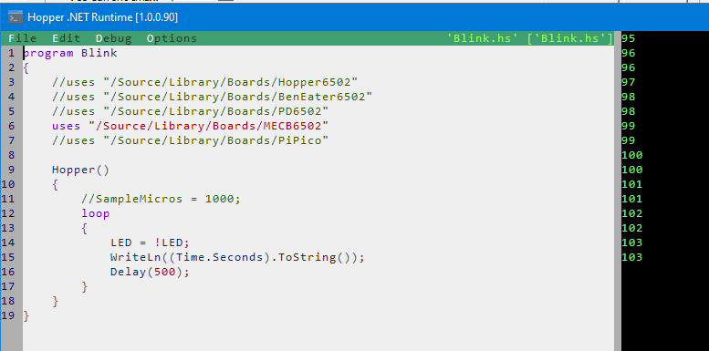
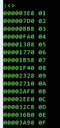
Sadly, it appears I'm not quite done yet. I am getting 1000 ticks on each blink of my LED and output to serial (TICKS0..3 increments in multiples of 0x03E8 as expected).
However, the delay between each tick is much longer than 1 second. This applies for setting the timer 1 latch to 1000 for 1Mhz and setting it to 4000 for 4MHz:
- ~42 seconds for each blink loop for the 1MHz case (latch set to 1000)
- ~2.75 seconds for each blink loop for the 4MHz case (I timed 5 loops and divided by 5) (latch set to 4000)
It isn't 'random' either : if I repeat the test from cold, I get exactly the same result.
My latest version is a hybrid of both lenzjo and epaell's work. The constants are here:
https://gist.github.com/sillycowvalley/ ... ink-asm-L9
The ISR and Initialization code are here:
https://gist.github.com/sillycowvalley/ ... nk-asm-L90
Disassembly in 'normal' 6502 syntax:
https://gist.github.com/sillycowvalley/ ... b00b93eff3
Can anyone spot a blunder?
Update : it must be something really silly that I'm just looking straight past because the version in the Hopper Runtime is perfectly calibrated.
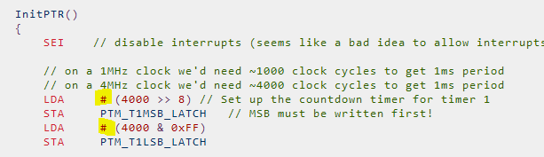
Solved: #!
Probably the most common 6502 Assembly typo by far (as-in, there is harmless one of these in Greg's "hello world").
Well, at least now I can move on knowing that all is good and the earth is still spinning correctly on its axis.
However, the delay between each tick is much longer than 1 second. This applies for setting the timer 1 latch to 1000 for 1Mhz and setting it to 4000 for 4MHz:
- ~42 seconds for each blink loop for the 1MHz case (latch set to 1000)
- ~2.75 seconds for each blink loop for the 4MHz case (I timed 5 loops and divided by 5) (latch set to 4000)
It isn't 'random' either : if I repeat the test from cold, I get exactly the same result.
My latest version is a hybrid of both lenzjo and epaell's work. The constants are here:
https://gist.github.com/sillycowvalley/ ... ink-asm-L9
The ISR and Initialization code are here:
https://gist.github.com/sillycowvalley/ ... nk-asm-L90
Disassembly in 'normal' 6502 syntax:
https://gist.github.com/sillycowvalley/ ... b00b93eff3
Can anyone spot a blunder?
Update : it must be something really silly that I'm just looking straight past because the version in the Hopper Runtime is perfectly calibrated.
Solved: #!
Probably the most common 6502 Assembly typo by far (as-in, there is harmless one of these in Greg's "hello world").
Well, at least now I can move on knowing that all is good and the earth is still spinning correctly on its axis.

Re: Motorola 6840 Programmable Timer Module (PTM)
Thanks for giving me something to smile at! It's been a very busy couple of days (you should have just received a shipping notification!).Michael wrote: Tue Jul 16, 2024 12:11 am Solved: #!
Probably the most common 6502 Assembly typo by far (as-in, there is harmless one of these in Greg's "hello world").
Well, at least now I can move on knowing that all is good and the earth is still spinning correctly on its axis.
I just thought I'd check-in with the Forum, to see what I've missed, before I dive back into some more KiCAD fun.
I'm glad to see you're making great progress, and solving those ever-arising challenges!