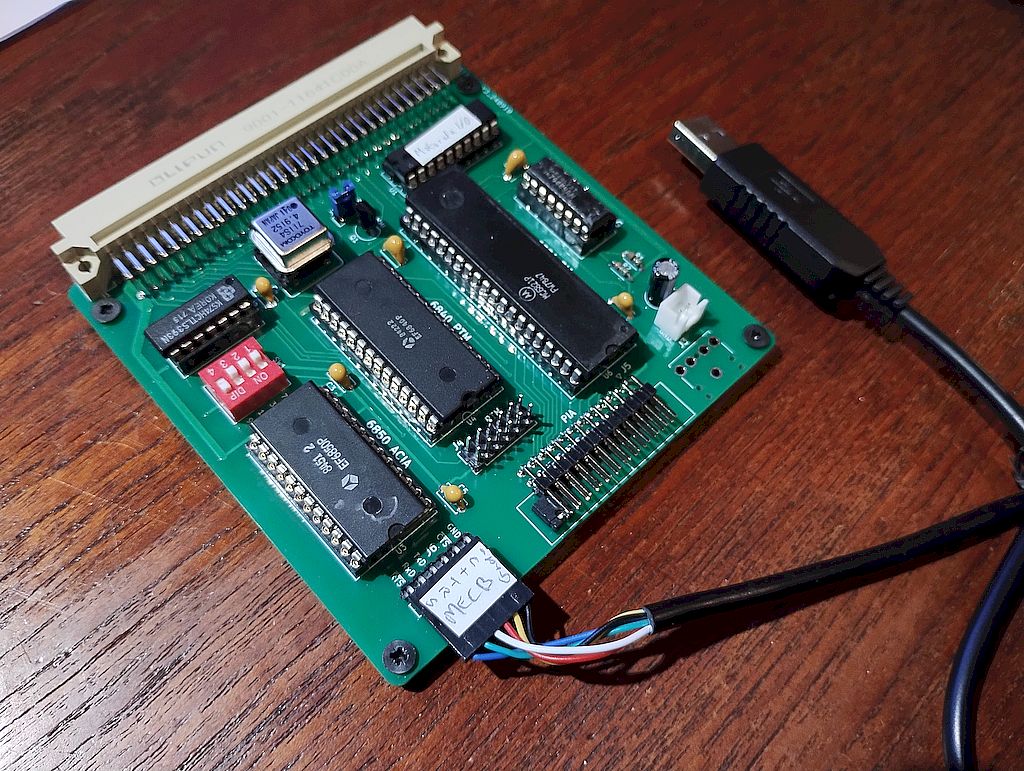
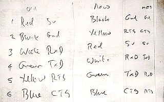
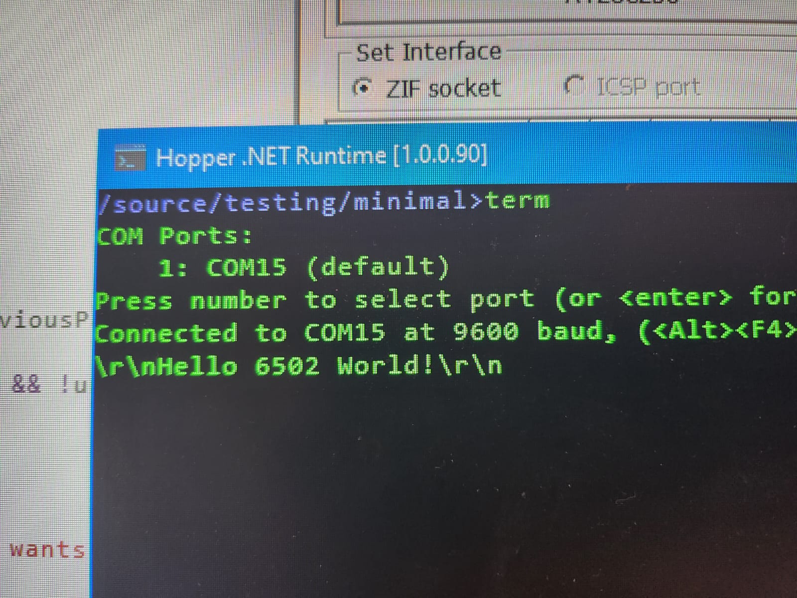
You were both correct:
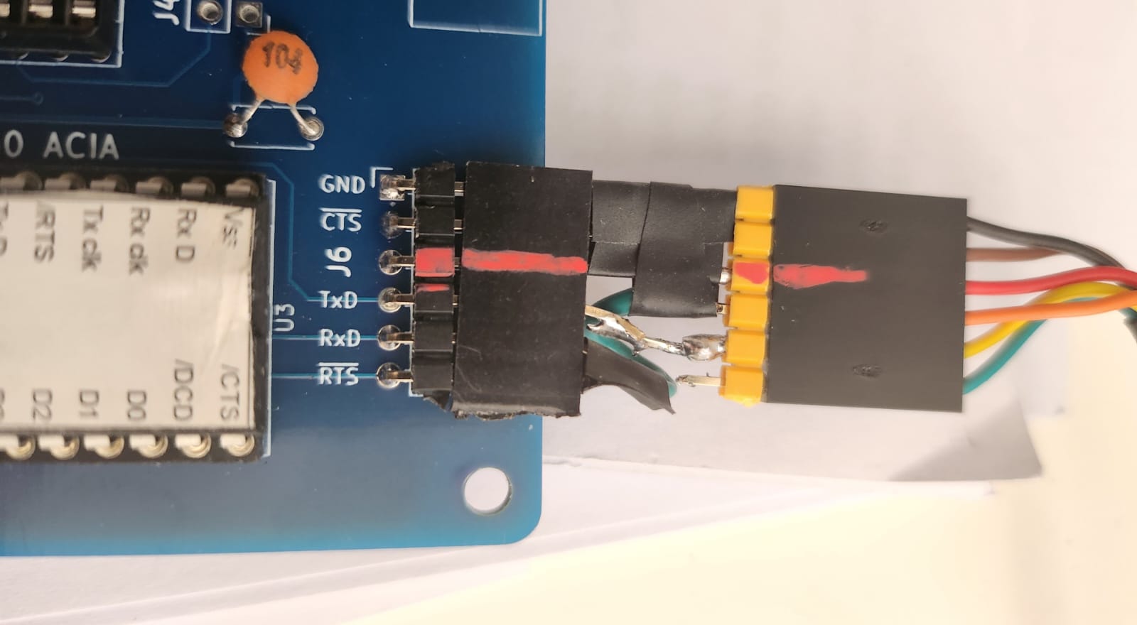
- first I corrected the Rx <-> Tx thing and still no joy ...
- then I grounded CTS and BOOM!
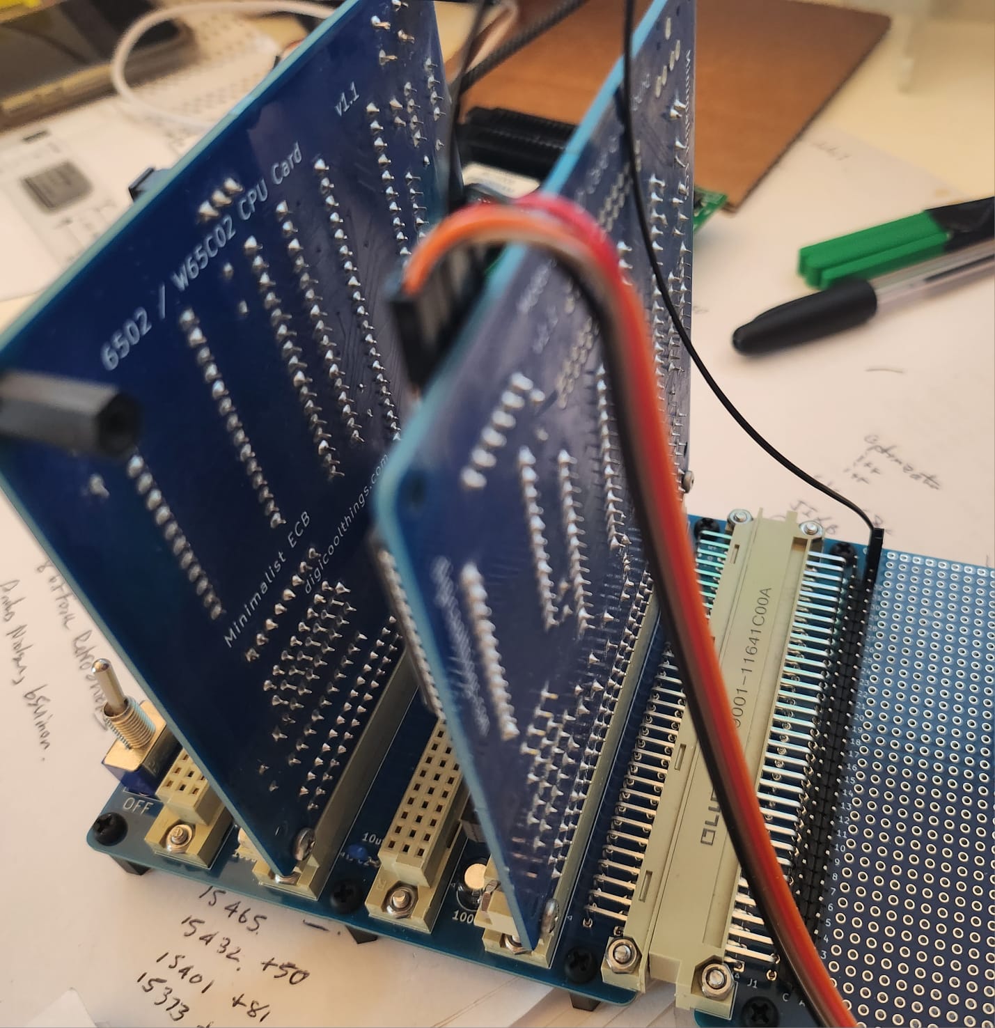
I notice the "FTDI" connector on your green PCB is the same pin-out as the connector on MECB (FTDI standard). Just that yours doesn't have the CTS / RTS pins, and mine doesn't have the 5V input pin.Michael wrote: ↑Sat Jul 13, 2024 2:50 pm The Tx and Rx on my board (the green one) correspond to the silk screen markings on the waveshare and velleman FTDI devices (and the pinout of the ftdichip.come cable connector.
The ones on the MECB I/O card correspond to the pins on the 6850!! (the opposite)
Pretty much. I followed the convention from the other FTDI devices that I have pinouts for : they are done from the perspective of the client connecting (and they are right there on the silkscreens of their little boards - would have been super confusing to have the opposite).
This is why do the SMD dance on all my boards, little chance of an error with a usb cableMichael wrote: ↑Sat Jul 13, 2024 11:27 pm
Pretty much. I followed the convention from the other FTDI devices that I have pinouts for : they are done from the perspective of the client connecting (and they are right there on the silkscreens of their little boards - would have been super confusing to have the opposite).
Grant Searle annotates both sides in his diagram but this sealed the deal for me in terms of what the 'standard' is for the most common cable plug. Your Tx and Rx pins are flipped which could be more of an issue than the silkscreen (I assume you have a cable that cleverly does the opposite?)
Yes, not a new problem, and I don't think there is a good answer other than "check!"
I grew up with "is it null modem or straight through", and, being horribly dislexic, I would keep flip-flopping the answer.
Hence the little red strips on all my connectors (I included 'CTS to GND' inside my little cross-over bodge connector).
Code: Select all
* CION - INPUT CONSOLE INITIALIZATION
* COON - OUTPUT CONSOLE INITIALIZATION
* A,X VOLATILE
CION   EQU      *
COON   LDA      #$3             ; RESET ACIA CODE
       LDX      <VECTAB+_ACIA   ; LOAD ACIA ADDRESS
       STA      ,X              ; STORE INTO STATUS REGISTER
       LDA      #$11            ; SET CONTROL
       STA      ,X              ; REGISTER UP
RTS    RTS                      ; RETURN TO CALLER
